This weekend I returned to a shelved project from several months ago, a complete 40 M QRP station built around the Easy Transmitter & Easy Receiver kit line from Pacific Antenna (QRPKits.com).
Why the Basic Pacific Antenna Kits?
I first became aware of these excellent basic kits a few years ago when we chose the Easy Receiver kit as a group build project for a Wednesday Workshop at the Yale Center for Engineering Innovation and Design that we, W1YU, the Amateur Radio Club at Yale University were hosting.
The CEID is a nicely equipped maker space at Yale and their Wednesday Workshop series allows students, faculty and staff to learn something new by making. Popular Wednesday Workshops have included chocolate making, woodworking, 3D printing and W1YU would program a workshop to introduce the uninitiated into radio fundamentals.
We chose the QRPKits.com 40-meter direct conversion receiver for one of our workshops because the kit was simple to build and able to be completed in less than two hours, was inexpensive, and had a reputation of working the first time. That night 20 CEID members, most of whom never soldered before, paired off into 10 teams and after a presentation on RF and a brief soldering tutorial, they got down to work. I’m very pleased to say that out of 10 kits attempted, all 10 worked, with only a couple needing nothing more than a touch up of a cold solder joint or two.
My Current Project
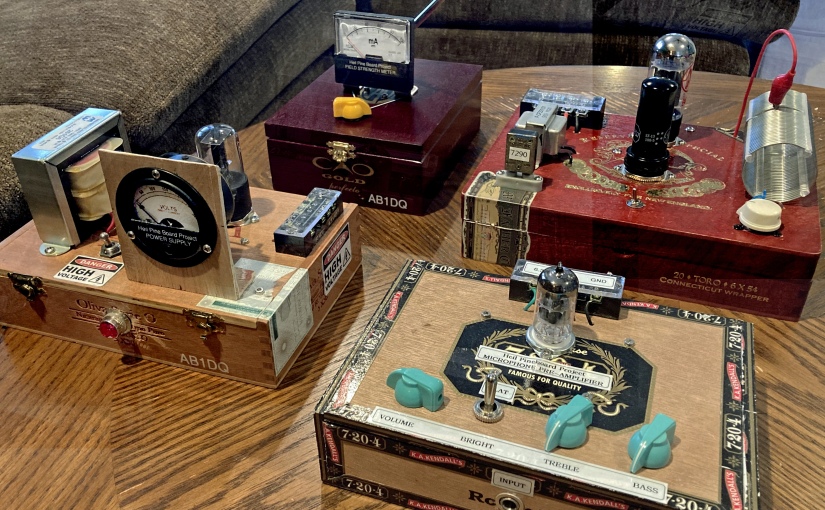
My initial plan was to build the Easy Receiver and Transmitter and mount them into a single enclosure (a cigar box) to make an all-in-one station. In addition to the receiver and transmitter, I had also planned to incorporate the Easy Audio Bandpass Filter, the Easy TR switch, and the Easy Low Pass Filter to limit out-of-band harmonics on transmit.
I had assembled all of the basic kits several months ago and as I often do, became sidetracked and never finished the project. I came across my circuit boards recently in my basement workshop and decided to pick up from where I left off.
I had previously completed the receiver, audio filter, TR switch and the low pass filter. The transmitter was still in its original packing, so this became my first project for the new year.

The completed project delivers 2.0 watts on all five frequencies.
A Couple of Modifications
I mentioned I came across the unfinished project in my basement recently. Over the past several months I have been working on organizing my workspace including inventorying and sorting the myriads of components I’ve managed to stockpile over the years. One of the things discovered in doing so was a variety packet of 40 and 80-meter HC-18U crystals for the QRP experimenter.
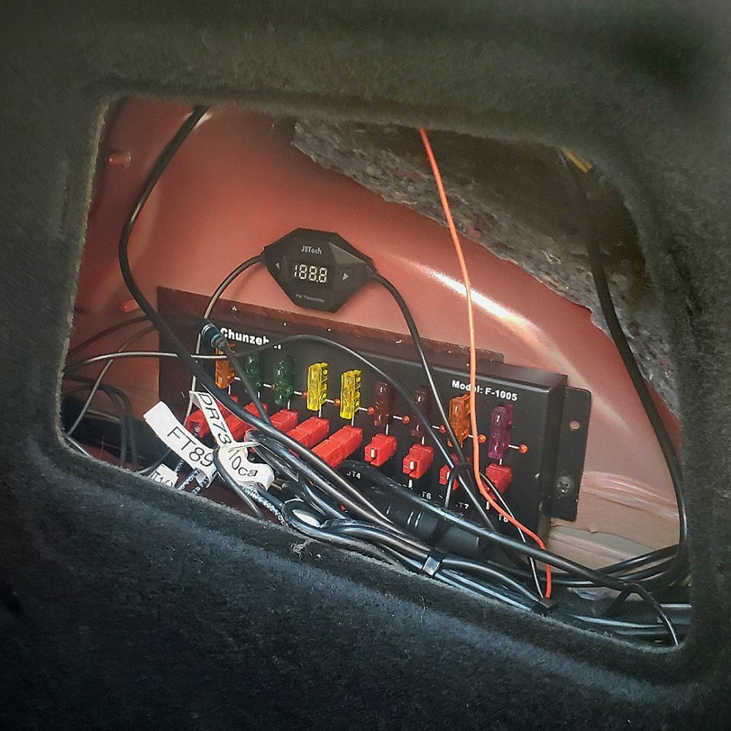
I decided I wanted to modify my transmitter build so instead of just being limited to the 7.040 crystal that came with the kit, I could easily select a different frequency by swapping crystals. The kit itself makes a provision as it includes a socket so the builder/operator could plug in a different crystal if they wanted to change frequencies.
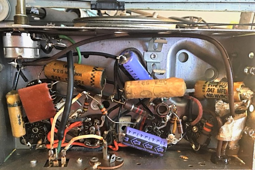
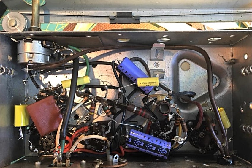
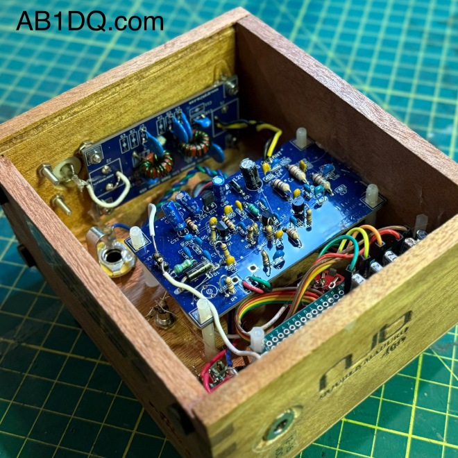
My modification takes the concept a step further. Creating a small bus board on which I mounted several crystals and connecting one end to a rotary switch, I was able to make changing frequency as easy as twisting a dial. My transmitter allows the operator to quickly choose between 7.030, 7.040, 7.055, 7.110 or 7.118 MHz.
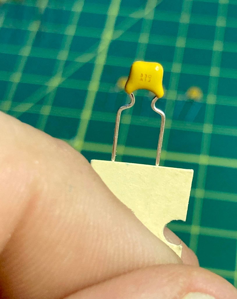
I made two other minor modifications. I incorporated the low-pass filter on board in the transmitter cabinet instead of as a stand-alone accessory, and I also added a yellow LED coupled with a 1K resistor to provide a power on pilot light on the front panel.

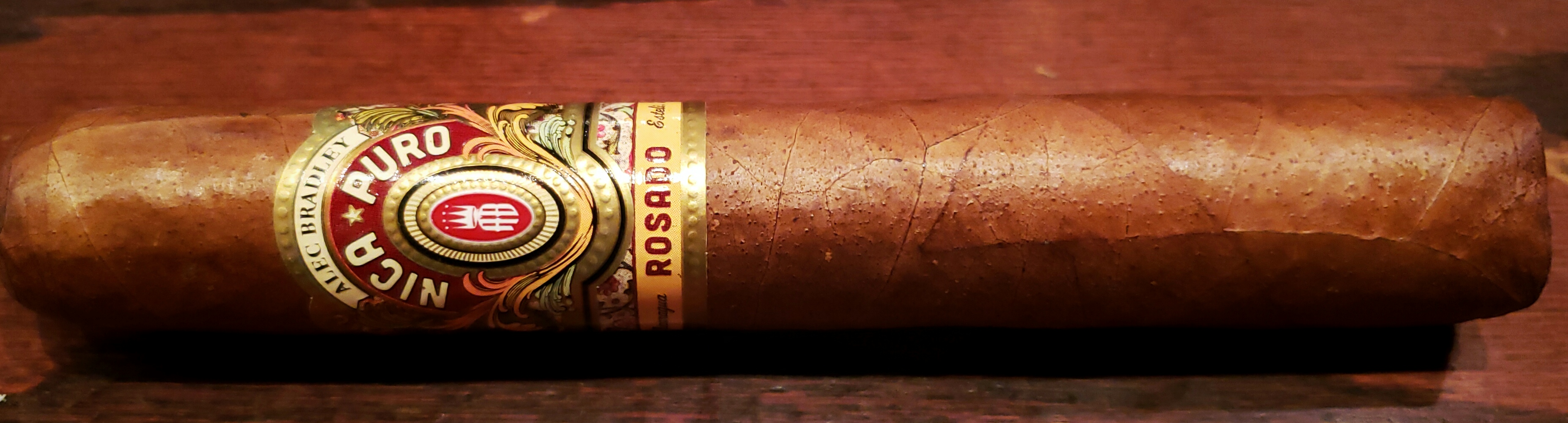
I used a small Nub cigar box for my cabinet. I sanded off some printing on the bottom surface and applied a nice cherry stain to the box. Orienting the box so I used the thin bottom as the front of the radio, I had no problem with short potentiometer shafts. The sides of the box were quite a bit thicker, however, and I needed to countersink the holes drilled for the SO239 antenna connector and the coaxial DC power socket.
Another nice feature of the Nub box is that it has a slide off lid, which now becomes the back panel of the radio. It makes for easy opening for repairs or adjustments – or for show and tell at the local club.
How does it work?
The Easy Transmitter Kit promises 2 to 2.5 watts output on the 40-meter band, and I am very pleased to report that indeed, I measured a solid 2.0 watts on all five frequencies. The circuit includes a 5K potentiometer for fine tuning which allows a band spread of a few kHz. For the four lowest frequencies, I spotted my signal right on frequency with the fine tune knob set dead center. 7.118 was a bit off center, unlike the others, but still solidly within range of the fine tune control.
Needless to say, I was very impressed with the initial performance of the transmitter the first time I powered it up.
What’s Next?
I mentioned that I have already purchased and assembled the other kits in the QRPKits.com “Easy” line. I plan on mounting the 40 meter Easy Receiver and the Easy Bandpass Filter in two separate but matching Nub cigar boxes. I plan to mount a speaker in bandpass filter cabinet and include a headphone jack, and to not include any speaker on the receiver. I plan to either use the receiver with earphones (my preferred means for operating CW) or will use a 3.5mm jumper to feed the bandpass filter/speaker unit.
I am contemplating building a small linear amplifier to give myself a boost as needed. QRPKits.com and QRP-Labs.com each offer a simple RF amplifier at a low price that promise to boost 2 watts into the 7-10 watts out range.
I highly recommend the QRPKits.com Easy series of kits for the aspiring kit builder or the old timer, like me. As priced, they remain a great value, and the kits are easy to assemble and best of all – have always worked as advertised.
I plan to blog about the matching receiver and audio amp/bandpass filter as I manage to complete those projects. Have you built any of the QRPKits.com kits? What was your experience? Drop me a line and let me know how you fared at james@ab1dq.com.
Thanks for stopping by my blog & 73!
©2025 JMSurprenant & ab1dq.com.