
A photo gallery from the New England Vintage Electronics Expo 5 held at the Courtyard Marriott in Nashua, NH on March 6, 2022


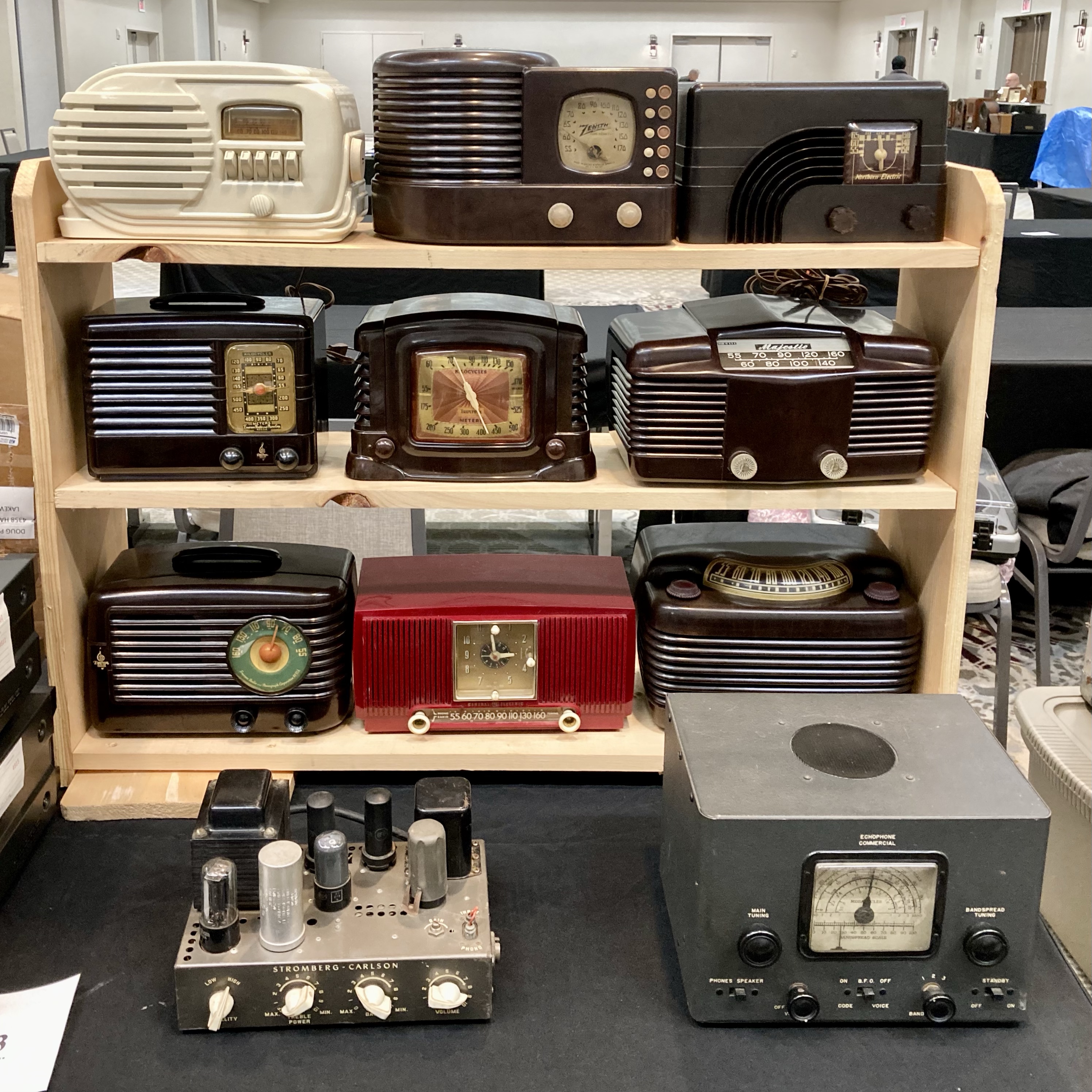


A photo gallery from the New England Vintage Electronics Expo 5 held at the Courtyard Marriott in Nashua, NH on March 6, 2022
Today I traveled back to the Merrimack Valley to visit a high school buddy, Larry, who like me, has caught the vintage electronics bug.
An increasing number of vintage radios, phonographs and – gasp – 8-track players – have been finding their way to Larry’s home, and as you might expect, most need a little TLC to return them to fully functional status.
I have helped Larry in the past, having recapped his 1937 Philco console AM radio and having done a full restoration of his Westinghouse “Little Jewel” H126 ‘refrigerator’ radio.
Larry was under the mis-perception that I am some sort of electronics genius because I was able to resuscitate those dead radios back to life. Ha! So when he recently called me asking for help with his 1940s era Admiral console radio and phonograph that had a low volume problem, I thought it was a good time to stop giving Larry fishes and give him a fishing lesson.
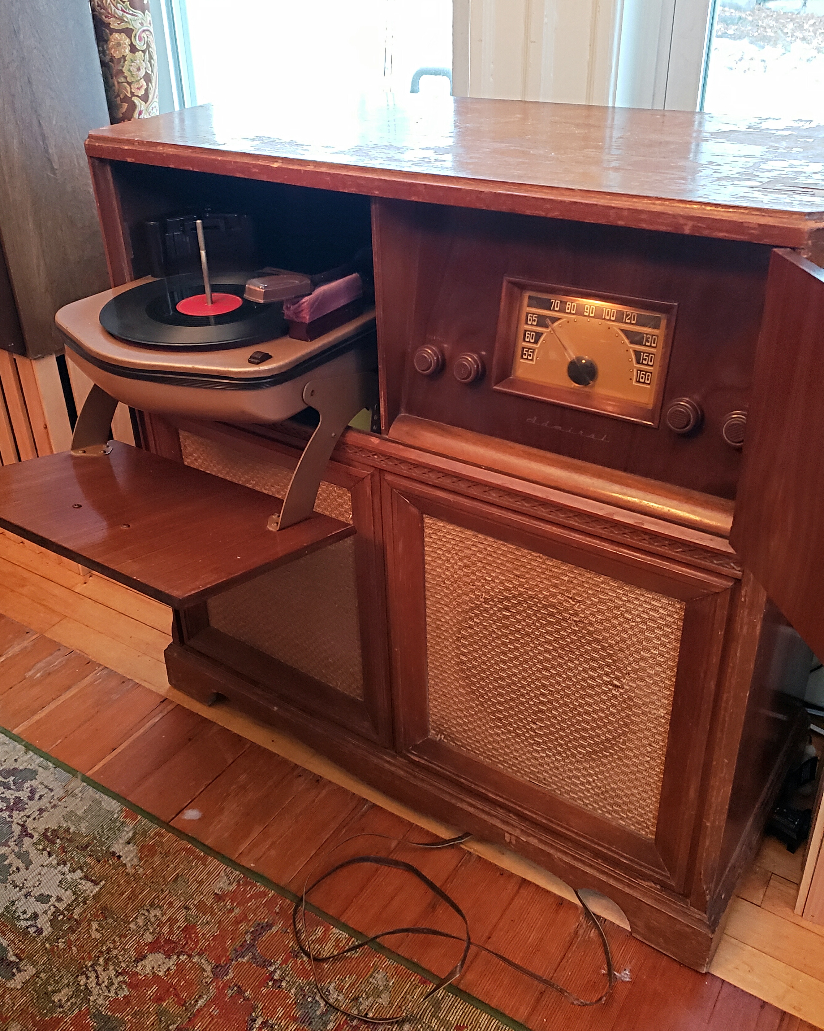
The Admiral 7CS5W is a 1948 6 tube superheterodyne AM band only radio receiver with a 78 RPM record changer in a side-by-each console arrangement. Larry’s complaint was that whether the radio or the phonograph was playing, the volume was too low.
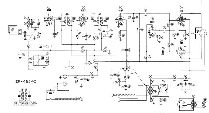
We downloaded the set schematics from the www.radiomuseum.org website and I showed Larry how to read the schematic, working from left to right, identifying the different stages of the radio circuit. We focused on the final audio stage which included a 6SQ7 phase inverter and a pair of 6K6 power output tubes.
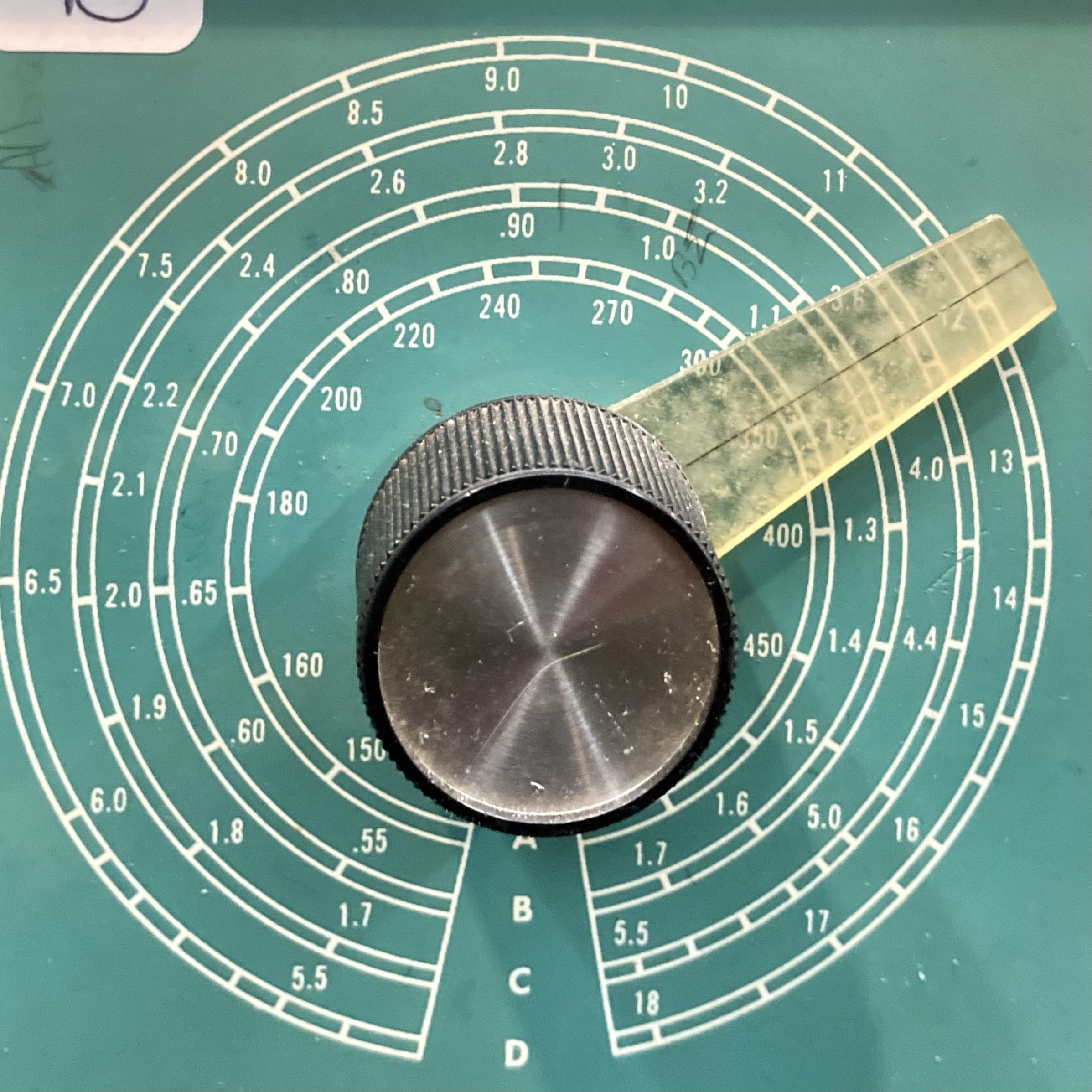
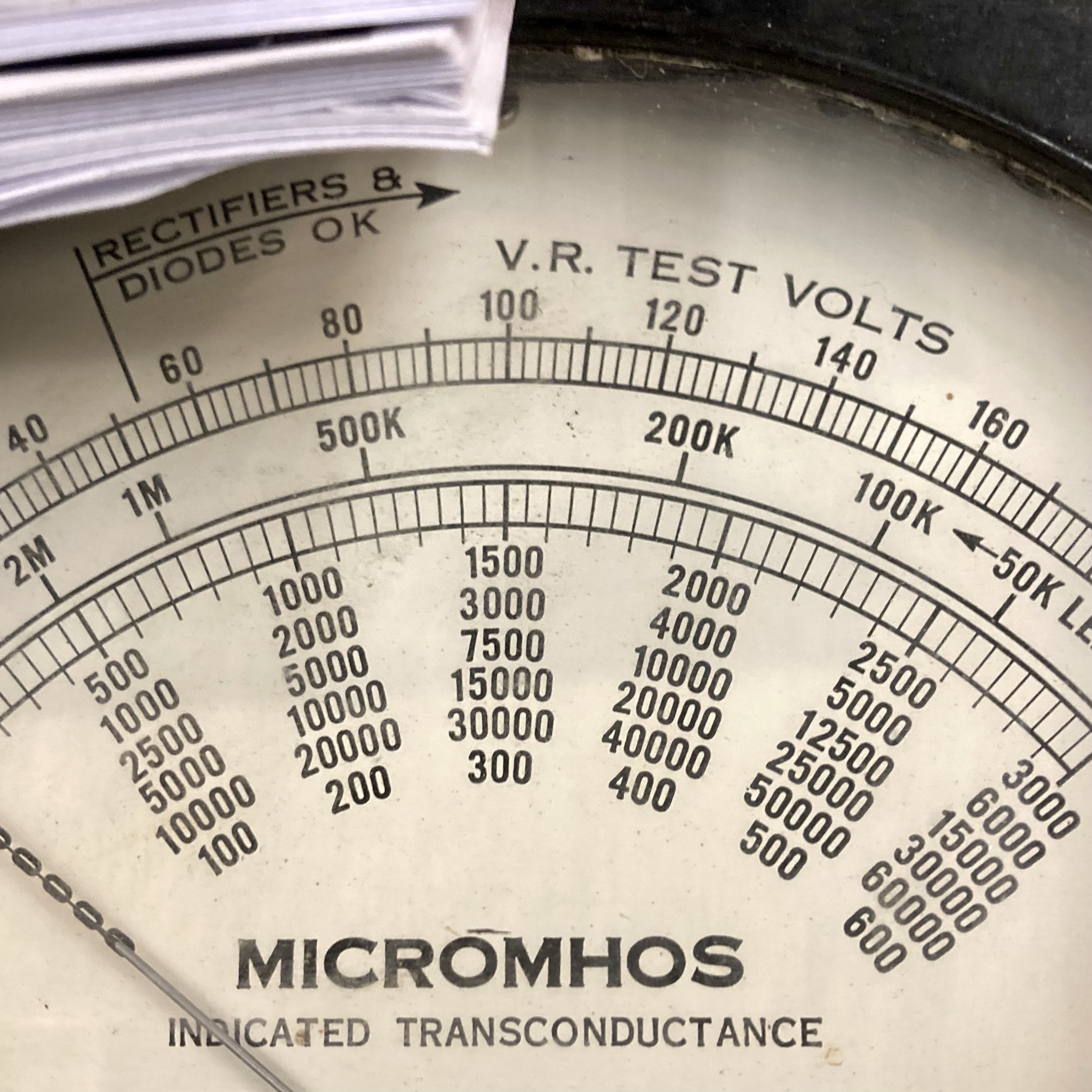
We started our work by testing all of the tubes, starting with the above named audio stage tubes, using my grandfather’s EMC 205 tube tester. We tested all tubes for shorts and quality and all passed.
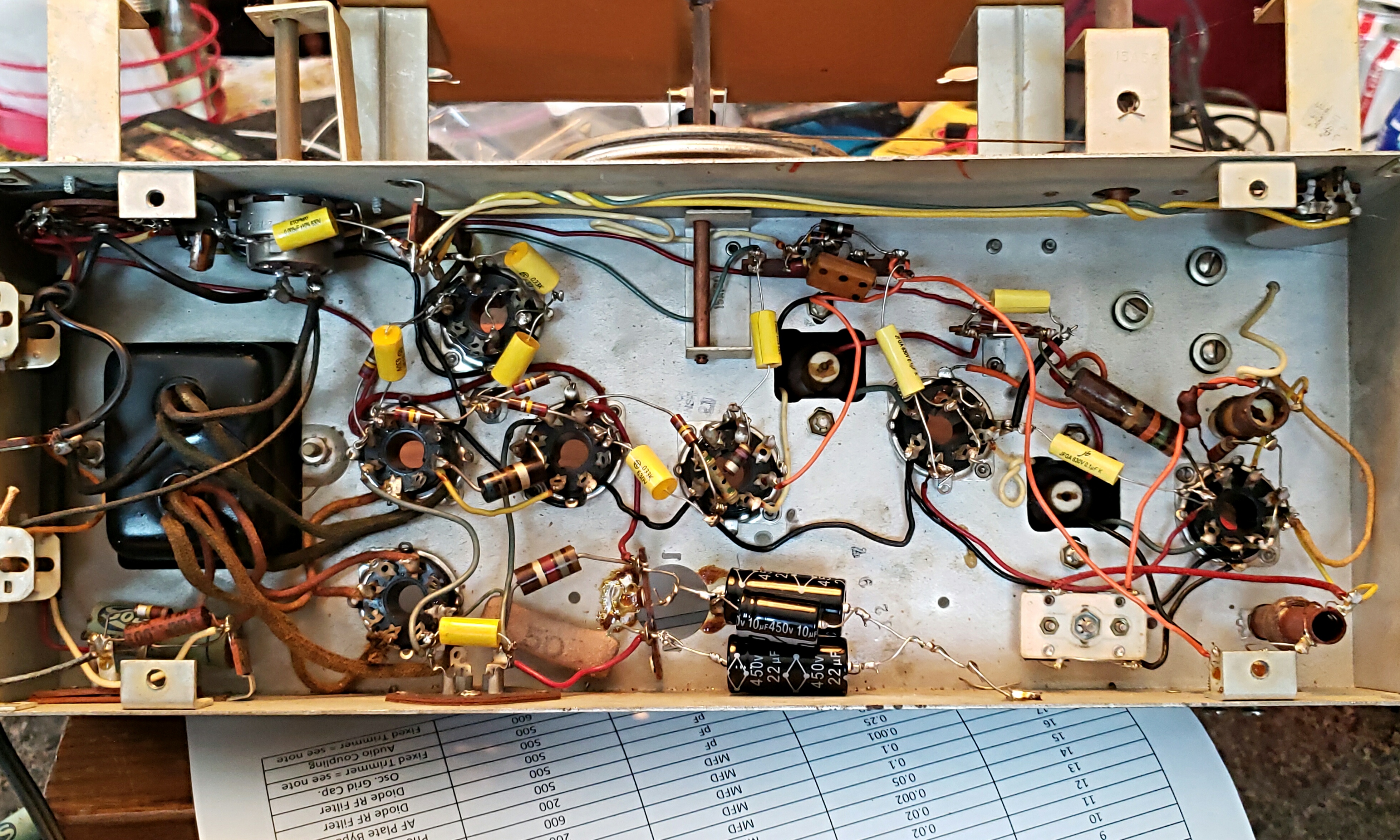
It was time to pull the chassis and see what was going on underneath. Looking at the chassis, I immediately noticed a hole where the original canned filter caps would have been – clearly someone had already serviced the radio and had replaced the electrolytic capacitors.

I was mildly concerned that because the tubes tested good, as they did, and someone had recently recapped the radio, the low audio problem was going to be more complex to solve.
We discovered that while someone indeed had previously serviced the radio, and had replaced the two electrolytic capacitors, he only replaced about half of the wax caps. Also more interestingly, those replacement caps did not look that new. The electrolytic capacitors were a pair of large General Electric cap that I’ve never seen before. The other replacement caps were a variety of blue-green paper caps that I was also unfamiliar with. I would have to guess that this radio was last serviced in the 1970s or early 1980s.

So, starting with the filters, we recapped the entire set. Larry was a quick student, absorbing what I taught him about how capacitors function and why they need to be replaced – see my previous blog post about recapping The Glendon RCA receiver.
We needed to manufacture a pair of 30 MFD electrolytic caps as the stock I brought did not have that value. For each we wired a 10 MFD and a 22 MFD in parallel to produce a pair of 32 MFD capacitors. When working with old radio circuits, capacitor values aren’t critical. As long as the replacement caps has the correct voltage rating or higher, it’s generally o.k. to replace the original with a higher value. For the .002 MFD caps in the Admiral, we used .005 MFD replacements.


After about 2 hours work and a lot of good conversation, we had the two electrolytic caps and ten of the wax and paper caps replaced.
Now was the moment of truth – would the recapping improve the low audio? Only one way to find out. We put the tubes back in, reinstalled the chassis in the cabinet and reconnected the speaker, antenna, and phono connectors and braced ourselves for the ‘smoke test.’ How did we do?

Replacing the capacitors completely resolved the low volume problem. The radio and phonograph ought to be good for the next 30 years.
In the end we saved another beautiful old radio , we launched Larry on the road of vintage electronics repair while catching up and I also disavowed him of his mis-perception that I’m some sort of a genius – not a bad Saturday at all.
©2019 JMSurprenant
At the 2018 New England Antique Radio Club Radio and Vintage Electronics Show, I had the good fortune of winning not one, but two door prizes!
The first was a circa 1955 RCA Model 6-XD-5A “The Glendon” AM broadcast receiver. The radio was promised to be ‘operational’ but ‘not restored.’ The second prize was a coupon to WJOE Radio, a favorite local vendor for radio restoration parts who also attends the NEARC Show each winter. I used the coupon to stock up on a couple of capacitor assortment boxes realizing I could use the capacitors to recap the Glendon at some point.
That “some point” came just two months later in April when after listening to the radio for just about an hour and a half I heard a loud sizzling sound, followed by a loud “pop!” and then loud buzzing from the speakers.
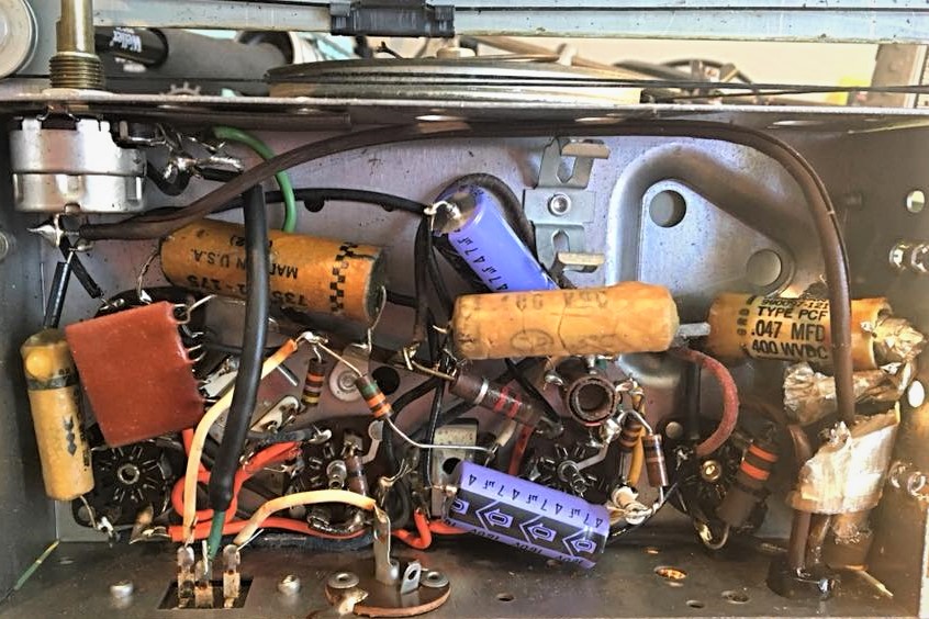
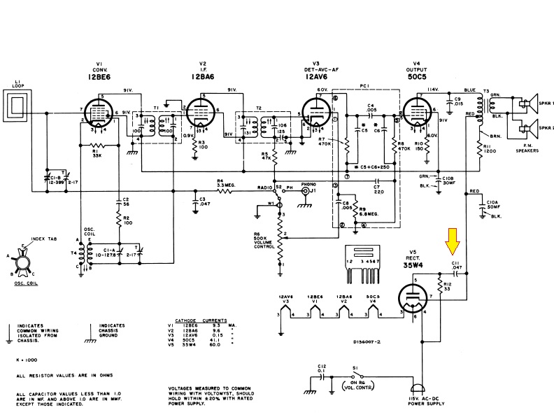
Sure enough, upon opening the set up I discovered that one of the wax capacitors, No. C11, on the power line had exploded.

A lot of folks are under the misimpression that when restoring old radios, the number one problem is that the old tubes have gone bad and that finding replacements is hard and expensive. The truth of the matter is the absolute number one affliction that antique radios suffer is failing capacitors. Replacement caps are plentiful, and inexpensive and many radios can be brought back to useable life by just recapping the set.
Over time wax and paper capacitors fail and the dielectric in large filter caps either dries up has leaked out. A capacitor that fails appears in circuit as a resistor and will not block DC while allowing AC signals to pass as they should. A sure sign that caps have failed in vintage radios is the presence of a predominant loud hum on the audio output.
Replacing capacitors is generally straight forward and easy. It’s simply a matter of removing the old capacitors and replacing them with modern day equivalents. Many times, you can easily read the values off the old capacitor once it is removed, but it’s also always a good idea to download a copy of the schematic and work from that.
There are two values you need to be concerned with when replacing capacitors – the capacitance value and the voltage rating.
Capacitance is measured in farads – typically microfarads (MFD) or in picofarads (pF). 1 farad is equal to 1,000,000 microfarad, or 1,000,000,000,000 picofarad.
When replacing capacitors, an exact match for the capacitance value is seldom critical, especially when working with consumer grade AM radio circuits. If you are unable to find a replacement cap with the same value, it is generally o.k. to use a close or higher value capacitor in the circuit.
You can also combine capacitors together to create a capacitor with the proper value. The math is simple – if you connect capacitors in parallel, their value equals the sum of the individual capacitors.

The second value you need to be concerned with when replacing capacitors is the voltage rating which is often abbreviated WVDC (working voltage, direct current) on the capacitor and on the schematic. Always be sure to replace capacitors with new units that are rated at the same working voltage or higher.
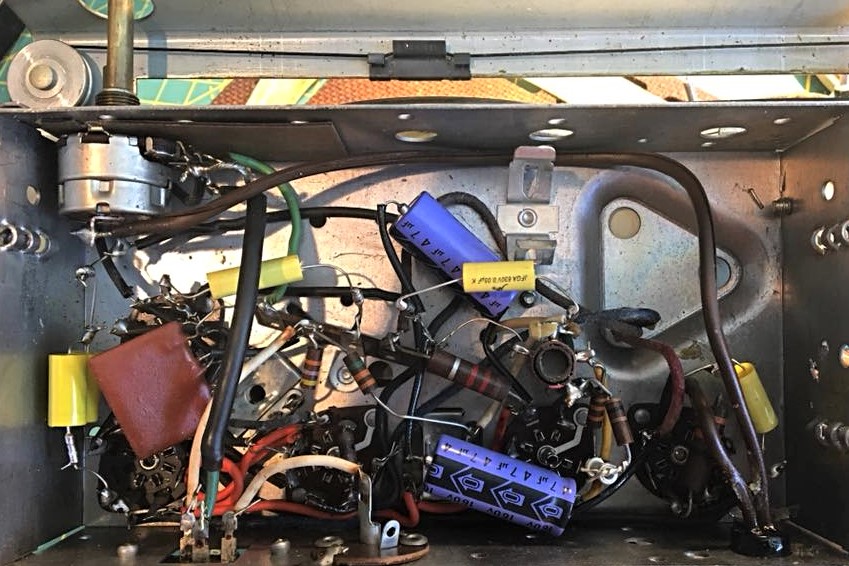
So, returning to The Glendon, I replaced C11 and all the other wax capacitors. I noticed that the previous owner had replaced the electrolytic filter caps already. The schematic called for a 30 MFD and a 50 MFD filter cap. The previous owner installed a pair of 450 volt 47 MFD caps so I left well enough alone.

Sure enough, my recap job brought this fine old radio back to life and it spent last summer as my chair-side radio on the front porch for Red Sox games. And what a year it was for listening to Boston baseball on the radio!

RCA VICTOR CO., INC. MODELN 6-XD-5C “THE GLENDON” SPECS:
Year: 1954/1955
Tubes: 12BE6 12BA6 12AV6 50C5 35W4
Circuit type: Super-Heterodyne IF 455 kHz; 2 AF stage(s)
Tuned circuits:6 AM circuit(s)
Bands: AM BCB only, 540 – 1600 kHz
Loudspeaker: 2 Loudspeakers / Ø 4 inch = 10.2 cm (not stereo)
Power out:1 W (1.5 W max.)
Material: Plastic
Dimensions (WHD): 12.5 x 7.5 x 6.375 inch
Antenna: Build in loop antenna
Power consumption: 35 watts.
Other: has audio input jack to connect Victrola record player.
©2019 JMSurprenant


_Model_205,_Made_In_USA,_Circa_1945_(14729252040).jpg)