This past winter, my old high school buddy, who we shall call “Laurence” handed off to me his Zenith Model G724 radio, a nice 1950 Bakelite case table top AM/FM superhet. According to Larry, the radio played well but had a broken dial string.
Dial strings can easily be replaced using common twine, and while I had the radio apart, it made good sense to replace the old wax and electrolytic capacitors and to test the tubes – simple basic maintenance to keep this radio working.
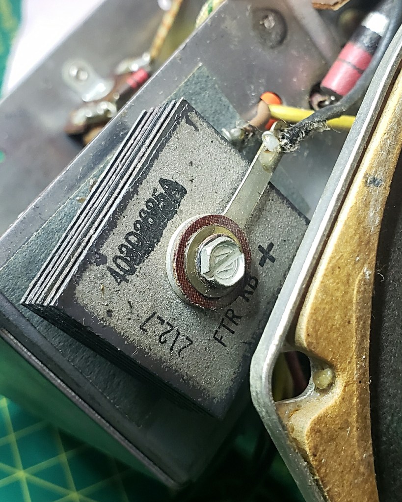
This radio has a selenium rectifier to convert AC to DC [Figure F, below]. While I was aware that selenium rectifiers are prone to failure as they age, I have never experienced a failure – most of the radios I have serviced feature tube rectifiers.
Laurence had shared my Facebook post about the service I had done to his radio on a vintage radio forum where an astute member spotted the selenium rectifier and asked if I planned to swap it out for a diode.
I decided I needed to broaden my knowledge of selenium rectifiers and what happens when they do fail. I came across two useful YouTube videos from two content providers I already subscribed to – Shango066 and All American Five Radio – that helped me fill my knowledge gap.
What I learned from both videos was that selenium rectifiers put out reduced voltage as they age, not delivering enough B+ voltage for the tubes. I also learned that if the selenium rectifier shorted out and overheated it would smell pretty awful and could cause more damage to the radio.
A modern general purpose rectifier diode, the 1N4007 can be used as a direct replacement for the selenium rectifier, however the selenium rectifier has a higher internal resistance than the 1N4007 which means a dropping resistor needs to be added in series with the diode to prevent tube filaments from burning out due to too much voltage.
In order to determine the value of the dropping resistor, I consulted the Sam’s Photofact and studied the schematic and voltage notes to find a reference voltage. According to my documentation, the grid voltage on pin 5 should be 125 VDC+.
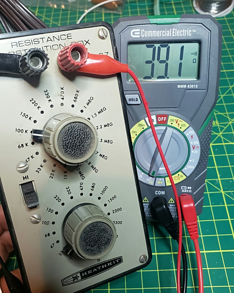
Using jumper cables I placed the 1N4007 in circuit with my Heathkit Resistance Subsitution Box in series and my Voltmeter connected to pin 5 of the 35B5.
With the resistance set to 33 ohms, the voltage on pin 5 was 124.9 volts. [Figure A., below]
Because the resistance substitution box was old, I wanted to check the resistance with my ohm meter – I discovered that the 33 ohm setting actually read at 39.1 ohms. [Figure B., below]
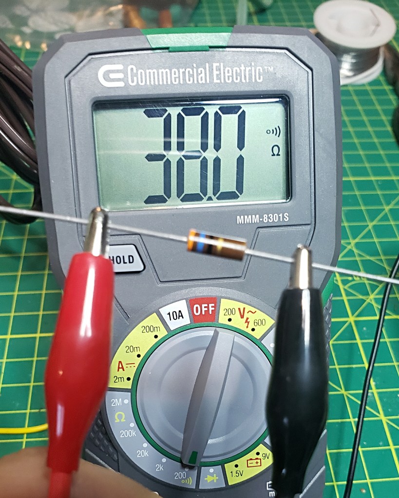
I chose a 36 ohm 1 watt resistor from my parts box for substitution and when I tested it with the ohm meter and it read 38.0 ohms. [Figure C., below]
FIGURE A.
FIGURE B.
FIGURE C.
FIGURE D.
FIGURE E.
FIGURE F.
I soldered the 36 ohm resistor in series with the 1N4007 diode and soldered it into circuit. [Figure D., above]
I then tested the voltage on pin 5 of 35B5 and found the substitution worked fine as the voltage reading was now 128.8 VDC+. [Figure E., above]
In the end, Laurence gets a tuned up Zenith and the next time I see him, I shall collect my friends and family fee – 2 snorts of Jack Daniels Whisky! 🙂
Please leave your comments on this site, or drop me a line at James@ab1dq.com!
Today I traveled back to the Merrimack Valley to visit a high school buddy, Larry, who like me, has caught the vintage electronics bug.
An increasing number of vintage radios, phonographs and – gasp – 8-track players – have been finding their way to Larry’s home, and as you might expect, most need a little TLC to return them to fully functional status.
Larry was under the mis-perception that I am some sort of electronics genius because I was able to resuscitate those dead radios back to life. Ha! So when he recently called me asking for help with his 1940s era Admiral console radio and phonograph that had a low volume problem, I thought it was a good time to stop giving Larry fishes and give him a fishing lesson.
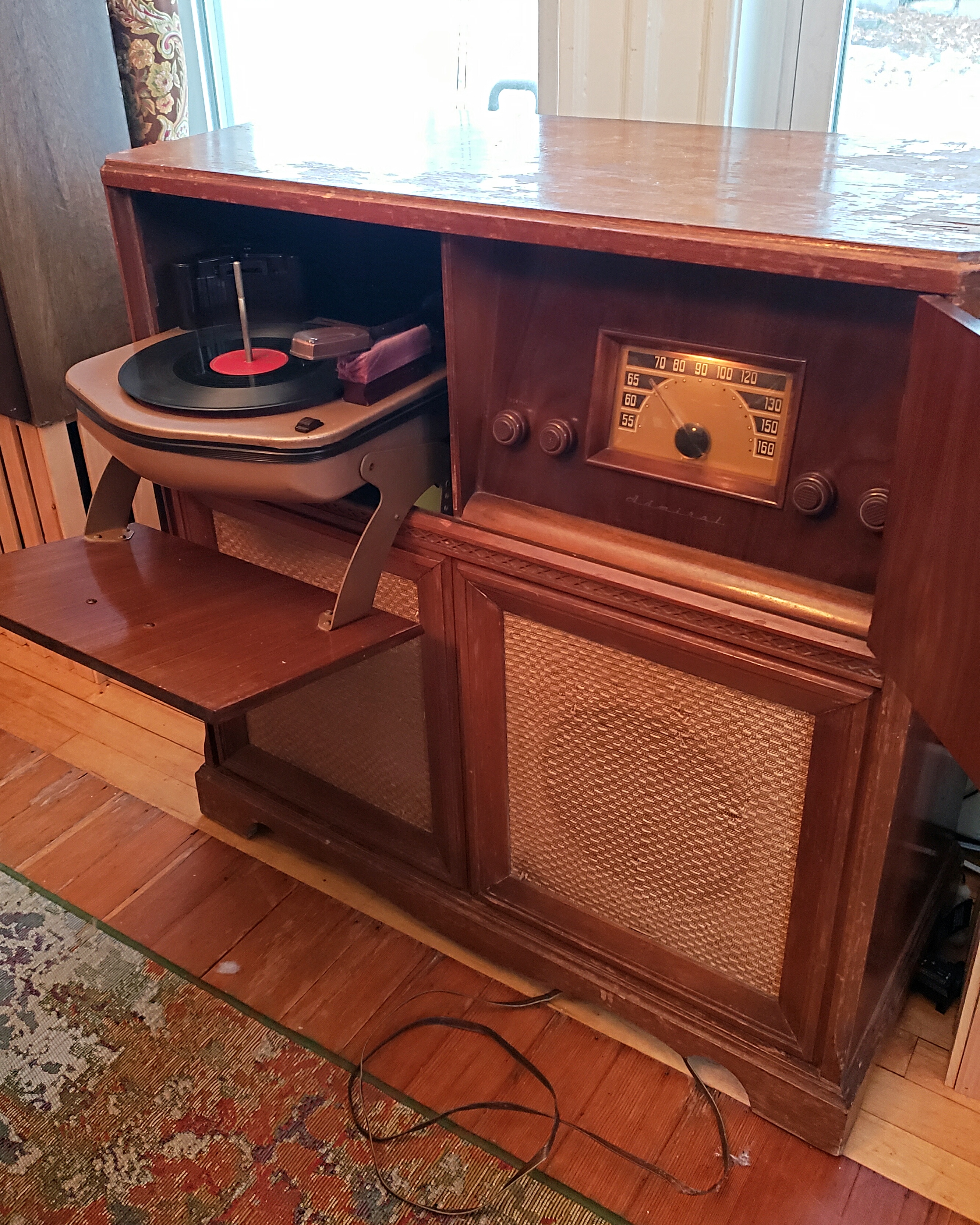
The Admiral 7CS5W is a 1948 6 tube superheterodyne AM band only radio receiver with a 78 RPM record changer in a side-by-each console arrangement. Larry’s complaint was that whether the radio or the phonograph was playing, the volume was too low.
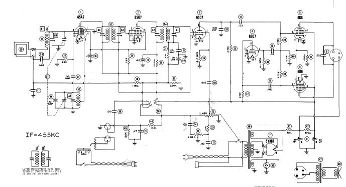
We downloaded the set schematics from the www.radiomuseum.org website and I showed Larry how to read the schematic, working from left to right, identifying the different stages of the radio circuit. We focused on the final audio stage which included a 6SQ7 phase inverter and a pair of 6K6 power output tubes.
Admrial 7CS5W Schematic courtesy of the RadioMuseum.org
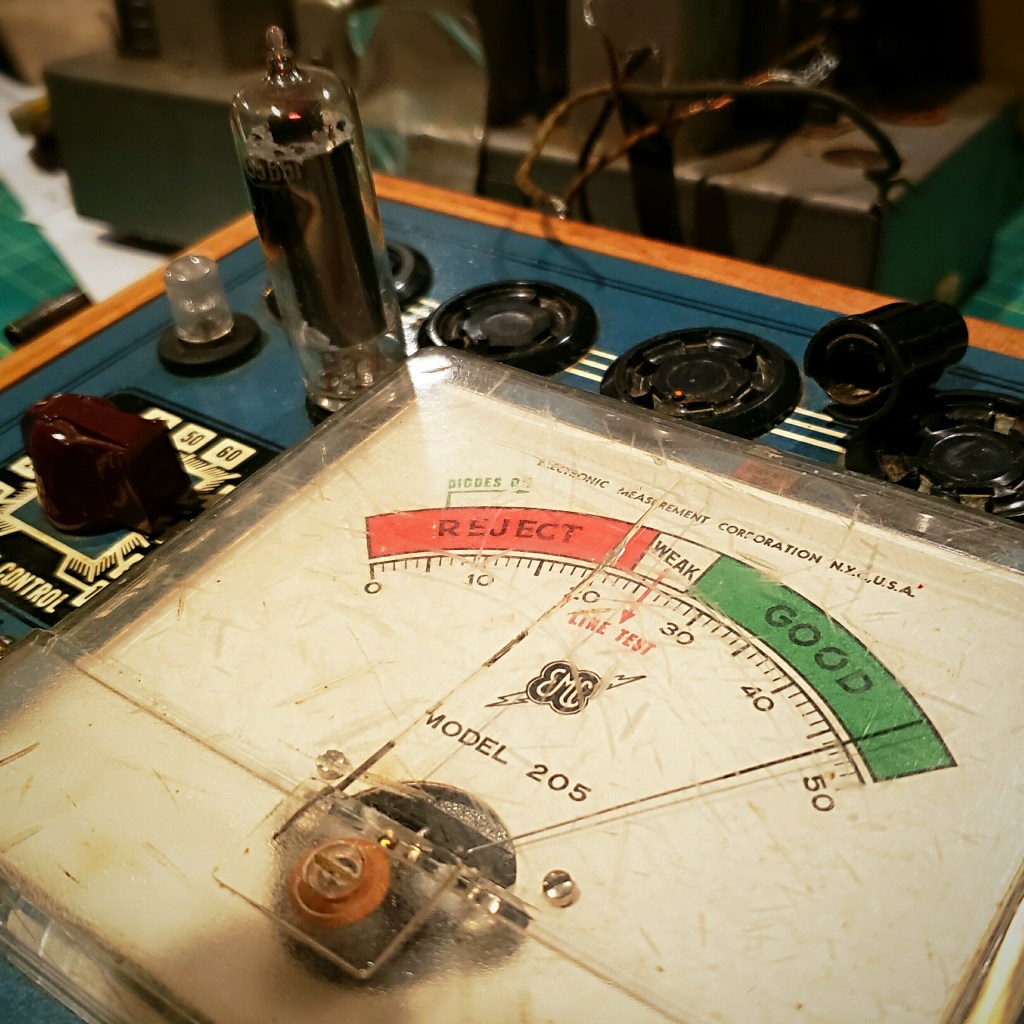
We started our work by testing all of the tubes, starting with the above named audio stage tubes, using my grandfather’s EMC 205 tube tester. We tested all tubes for shorts and quality and all passed.
It was time to pull the chassis and see what was going on underneath. Looking at the chassis, I immediately noticed a hole where the original canned filter caps would have been – clearly someone had already serviced the radio and had replaced the electrolytic capacitors.
The hole in the chassis suggested that someone had previously serviced this radio and replaced at least the filter caps.
I was mildly concerned that because the tubes tested good, as they did, and someone had recently recapped the radio, the low audio problem was going to be more complex to solve.
We discovered that while someone indeed had previously serviced the radio, and had replaced the two electrolytic capacitors, he only replaced about half of the wax caps. Also more interestingly, those replacement caps did not look that new. The electrolytic capacitors were a pair of large General Electric cap that I’ve never seen before. The other replacement caps were a variety of blue-green paper caps that I was also unfamiliar with. I would have to guess that this radio was last serviced in the 1970s or early 1980s.
BEFORE: Notice the big copper cylinder GE electrolytic caps an the blue paper caps on the right side of the chassis – the previous recap job was incomplete and apparently done some decades ago. It was time for this radio’s 30 year tune up.
So, starting with the filters, we recapped the entire set. Larry was a quick student, absorbing what I taught him about how capacitors function and why they need to be replaced – see my previous blog post about recapping The Glendon RCA receiver.
We needed to manufacture a pair of 30 MFD electrolytic caps as the stock I brought did not have that value. For each we wired a 10 MFD and a 22 MFD in parallel to produce a pair of 32 MFD capacitors. When working with old radio circuits, capacitor values aren’t critical. As long as the replacement caps has the correct voltage rating or higher, it’s generally o.k. to replace the original with a higher value. For the .002 MFD caps in the Admiral, we used .005 MFD replacements.
THEN: Larry = flashlight holder
NOW: Larry soldering in new caps
After about 2 hours work and a lot of good conversation, we had the two electrolytic caps and ten of the wax and paper caps replaced.
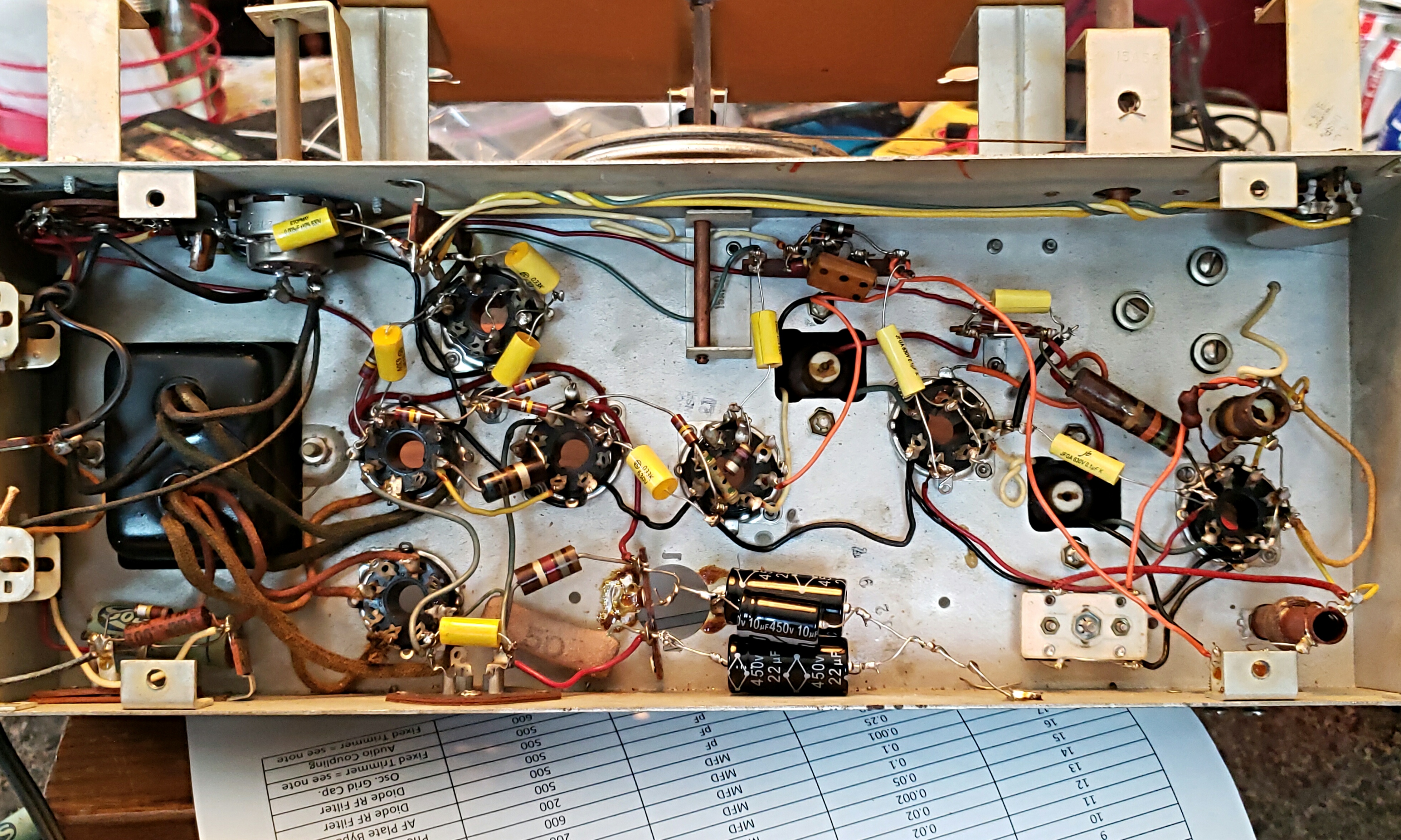
AFTER: Notice the ‘built up’ black electrolytic caps at the bottom of the chassis. We wired a pair of 10 MFD and 22 MFD capacitors together to make a pair of 32 MFD filter caps. Notice too how much less space the new yellow caps take up under the chassis.
Now was the moment of truth – would the recapping improve the low audio? Only one way to find out. We put the tubes back in, reinstalled the chassis in the cabinet and reconnected the speaker, antenna, and phono connectors and braced ourselves for the ‘smoke test.’ How did we do?
SUCCESS!
Replacing the capacitors completely resolved the low volume problem. The radio and phonograph ought to be good for the next 30 years.
In the end we saved another beautiful old radio , we launched Larry on the road of vintage electronics repair while catching up and I also disavowed him of his mis-perception that I’m some sort of a genius – not a bad Saturday at all.
One of the saddest things about my hobby of restoring vintage radios is the absolute lack of quality programming on the broadcast bands today.
Not only is the golden age of radio long gone, today’s AM airwaves are chockful of hate filled right wing talk and syndicated FM commercial radio is mostly insipid crap music. A couple of summers ago, I built a 2 tube regen radio receiver kit with my 10-year-old niece, and while the build was quality time spent together, in the end she was left with a radio that is of no use to her.
But, while there may be very little worth listening to on the broadcast bands today, there is no shortage of excellent programming available as podcasts – good music, true crime, documentaries, comedy and even drama – free for the taking for enjoyment on your smart phone or other device. This cornucopia of content can make ‘watching the radio’ wonderful again.
There are three easy ways to play modern podcasts and other recorded programs on a vintage radio.
The first is to add an “AUX IN” to a vintage radio, like many new radios have. The circuitry is simple and with a handful of parts, including a 1/8 stereo jack, you can easily play the output from your iPod, smart phone or CD player through the radio’s AF stage.
This “AUX IN” mod is popular with radio repair folk who restore vintage radios for resale. Look at what is available for sale on http://www.radioattic.com and you’ll find many radios for sale with the mod. If this interests you, check out the YouTubevideo by D-Lab Electronics here.
The second method is to add a Bluetooth receiver wired into the radio’s AF stage like the “AUX IN” jack mod above. This mod is attractive as the listener can easily transmit podcasts and music from their smart phone to the vintage radio.
For me, the third method that I am profiling here, using a low power transmitter to ‘broadcast’ programs to my vintage radios is a bit more authentic as ‘real radio’ transmitting a modulated RF signal to the receiver where the ‘whole radio’ is being used from the RF to the IF to the AF.
So, a few years ago I decided to build the SSTRAN AMT3000 transmitter kit. It is a popular solid state transmitter that costs about $100. As of this writing, it is not clear to me whether the kit is still available or not as the www.sstran.com website still has an announcement on the home page stating that as of November 12, 2017 they are not accepting any new orders. However the catalog page and shopping cart still appear functional.
I had considered other options including a scratch build or this $40 tube based AM transmitter kit. The tube option had two solid arguments going for it – it was definitely cheaper and using a tube-based transmitter seemed a better match stylistically for most of my antique radios as they are tube based.
However, the AMT3000 won out as it had a few qualities that the tube kit did not offer. These included separate up-front controls for gain, modulation and signal compression. The AMT3000 is also easily tuned to different frequencies on the AM broadcast band by setting DIP switches.
I had also read several online reviews and discovered that the kit had a very good reputation. The fit and finish were attractive too so the SSTRAN kit won out in the end.
I recall it took me two, maybe three evenings to construct the kit. The build was easy thanks to excellent documentation, good PCB layout and no toroids or coils to wind. There was a single surface mount IC, however, but it only has 14 leads and spacing was wide enough that I had no difficulty with my middle aged failing eyesight and shakier dexterity.
The completed circuit board.
In the top left view above you see there are two audio in jacks. This is a mono transmitter, but you can feed a stereo signal through the two jacks which are combined to mono. I use a stereo to RCA jack patch cable to connect the transmitter to my PC or CD player.
The transmitter comes with a wall wart step down transformer that puts out 11 VAC; the voltage regulator can be seen with the heatsink above.
A PLL synthesizer references the 4 MHz crystal to precisely set the transmit frequency. The DIP switches mentioned above to tune the transmitter is seen just below the heat sink on the voltage regulator. The manual includes a table showing the settings to tune across the AM broadcast band.
Notice the three RF chokes, which can be switched in or out of the circuit with jumpers to reduce hum caused by stray RF. Two chokes isolate the power input and the third isolates the audio input ground from the PCB ground.
On the right side of the board you will see a four position DIP switch used to switch several inductors in and out of circuit to assist tuning the indoor long wire antenna supplied with the kit. The instructions describe the construction of a base loaded vertical outdoor antenna that can be used to transmit up to a 2-mile radius which I have not built. When using the external antenna, these inductors are switched out.
For my purposes, I have setup my home AM broadcast station on the operating desk of my ham radio stationon the second floor of my house. As I amonly interested in transmitting a signal to radios within my house, I am usingthe provided long wire antenna which I have hanging out a second storywindow.
My transmitter is tuned to 1,000 kHz which is a relatively dead spot on the AM dial in New Haven County, despite the number of signals coming from NYC to the southwest and Boston to the Northeast. I get little interference day or night.
My transmitter is connected to a beater Dell laptop I bought refurbed from Walmart.com for a song. I installed Ubuntu and use the Beatbox app to manage the queue of podcasts and MP3s. I leave the station on 24/7 so now there is always something worth listening to on the radio.
I mentioned above that the AMT3000 has a compression control, which is a real nice touch. Turning down the compression increases the hi fidelity of the signal, music actually sounds better to my ears than what is typically heard from commercial AM stations.
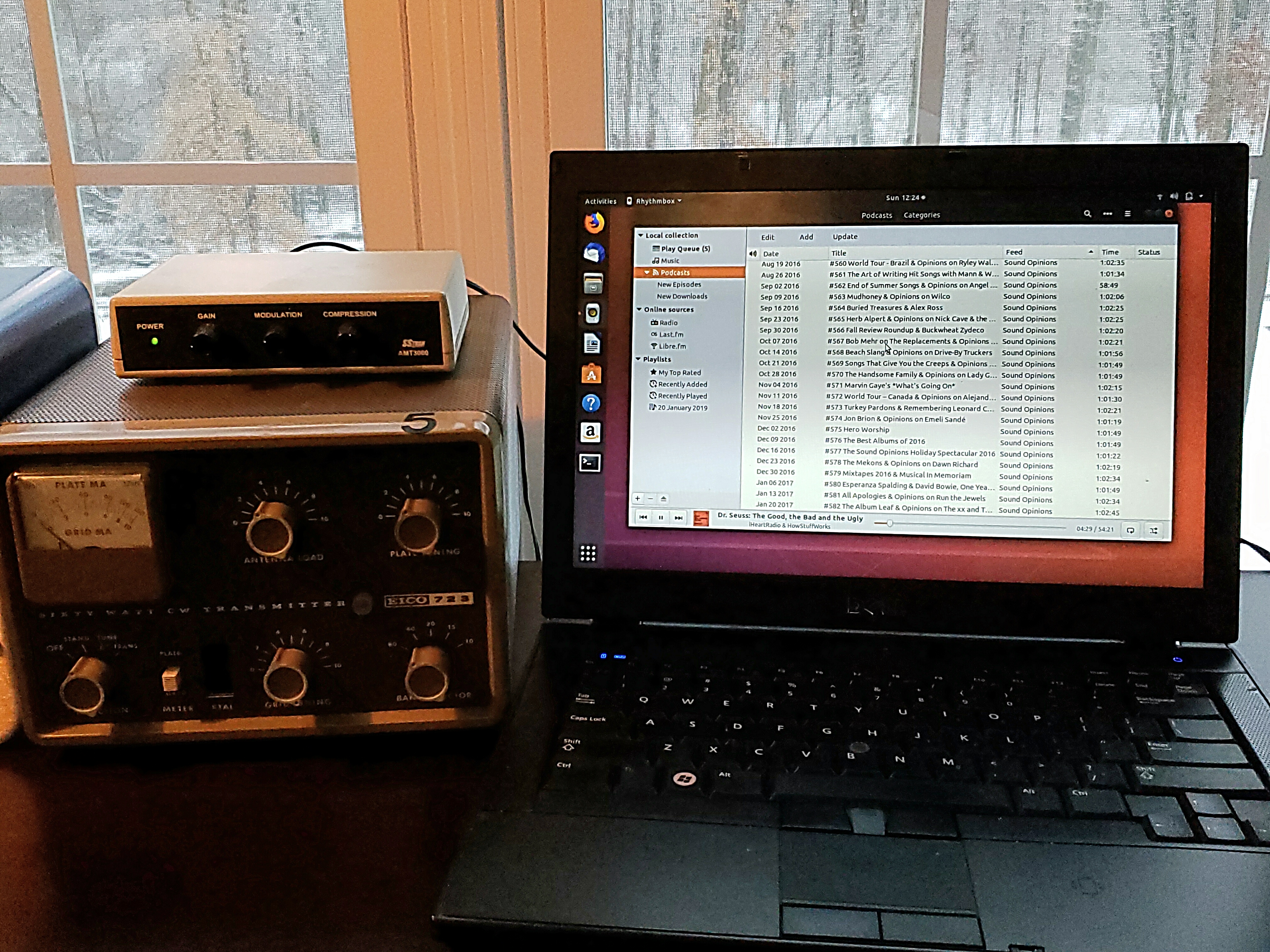
My home AM radio station – the SSTRAN AMT3000 transmitter sits atop my EICO 723 Novice transmitter on the AB1DQ operating bench. Programming is queued via the Beatbox app on my Ubuntu Dell laptop.
If you are looking for an AM transmitter to bring life back to your vintage radios, you won’t do any better than the SSTRAN AMT3000. It is a real solid performer and simple enough build for anyone with moderate soldering skills. I have gotten many years of satisfaction from mine. Every December I use it to transmit holiday music to vintage radios placed throughout our house during our annual Christmas party – it’s a fine way to showcase the radios I have lovingly restored.
SSTRAN AMT3000 SPECS:
FCC Part 15 Compliant
Emission type: A3 Amplitude Modulation.
Modulation Type: Series Modulation.
Modulation Capability: 100%
Carrier Shift: less than 0.5%
Broadcast Frequency Range: 530 kHz to 1705 kHzin 10 kHz increments (a 9kHz increment version is also available for non-US radios)
Frequency Response: 10Hz to 20kHz
Audio Input Level: 200mV for 100% modulation
Audio Input Impedance: 4 ohms to 50K ohms
Distortion: 0.5%
Final DC Input Power: 100 milliwatts (full legallimit per FCC Part 15)


_Model_205,_Made_In_USA,_Circa_1945_(14729252040).jpg)