A DIY 555 AM Transmitter

Build this low power dirty AM transmitter and learn about RF modulation.

In the 21st century we have all become accustomed to our connected high-tech lifestyle and we more or less take our internet based social and commercial connectivity for granted until the ‘network goes down.’ Much of the technology that drives our digital being are computer based, but another essential element is radio technology, without which we would find ourselves much less connected.

How does ‘radio’ work?

Long before manipulated radio waves were used to provide the backbone of today’s digital cellular and cloud based information network, those of us who grew up in the twentieth century knew radio primarily as a means to enjoy music, news and talk, via the AM and FM radios in our homes and cars. But what is radio?

Simply put, radio is the transmission and reception of electromagnetic waves that are encoded with data. The data could be spoken word, music, or digital data like text and email messages or larger digital files like software or other data files.

The data that can be transmitted via radio waves exists as low-energy signals and they must be attached to a high-energy signal called a carrier wave in order to be transmitted. A carrier wave is at a significantly higher frequency than the input signal and is typically sinusoidal.

The mixing of the signal with the carrier wave is a process called modulation. There are several ways a carrier can be modulated, the two most common modes of modulation for an audio signal is amplitude modulaion (AM) and frequency modulation (FM). (Another common method of modulation a carrier signal that is beyond the scope of this article is phase modulation (PM)).

Amplitude modulation involves varying the signal strength, or amplitude, of the carrier wave in direct proportion to the message signal. Frequency modulation involves varying the frequency of the carrier wave in dirrect proportion of the message signal.

AMPLITUDE MODULATION: A low energy audio electrical signal is mixed with a sinusoidal high energy carrier wave in the transmitter. This modulated signal is amplified and emitted from a transmitting antenna. The modulated signal is propagated through space and can be received by the antenna of a properly tuned remote radio set. The receiver demodultes or removes the carrier from the audio signal which is electronically enhanced and amplified and finally sent to the speaker where it can be heard and understood by the ear.

A simple low power AM radio transmitter

It is possible to construct a very simple low power transmitter built around the ubiquitous 555 Time Integrated Circuit which is capable of demonstrating the principle of amplitude modulation by mixing an audio signal with a carrier signal that can be transmitted to and received by a AM radio receiver.

The 555 timer chip was designed in 1971 by Hans Camenzind and has remained one of the most popular and versatile integrated circuit chips ever produced. Simple when compared to today’s chips which may contain tens of billions of transistors, the 555 has 25 bipoloar transistors, 15 resistors and 2 diodes.

The 555 chip has three distinct modes of operation – monostable, bistable, and astable.

The monostable mode is also known as the one-shot mode and will output a single pulse of current for a specified length of time. The bistable mode is also known as the flip-flop mode and alternates between two stable states, on and off, controlled by the trigger and reset pin.

The astable mode is also known as the oscillator mode and can be used to generate a carrier wave that could be modulated in a model RF transmitter circuit. We will employ this feature of the 555 chip for our transmitter circuit described below.

Traditionally the carrier wave in a radio transmitter is a continuous sinusoidal wave. However, the 555’s output is digital, either on or off, so the resulting wave is a square wave. An alterenating current sine wave is smooth and continuous and is optimal for carrying an information signal, but the square wave will work for our purposes.

SQUARE WAVE OSCILLATION: Rapid alternation between on and off signal states produces a square wave signal that can be used as a carrier wave in an RF circuit.

The circuit

I will now present and describe a simple AM radio transmitter circuit that you may wish to construct to observe and demonstrate radio modulation. This circuit design can be found on hundreds of websites oftentimes with small variations component value changes or minor modificaitons to the basic circuit. The circuit I present here is based on the core circuit, nominally modified to reflect what I have found to work well on my bench. I encourage readers who take the time to build my circuit to experiment and share modifications letting us know how you may have enhanced performance.

We will start by looking at the transmitter circuit by its three sub-circuits. The first is the oscillator circuit that produces the carrier wave, the second is the audio input sub-circuit, and thirdly we add the output amplifier and antenna.

1.) The Oscillator

The schematic diagram below is built upon the basic 555 astable circuit and this is the heart of the transmitter. The frequency of the carrier wave output on pin 3 is controlled by how rapidly capacitor C1 charges and discharges. The values of resistors R1, R3 and R4 will determine how quickly C1 charges.

When the charge of C1 reaches 2/3 of the control voltage Vcc, the output at pin 3 goes high. When the charge of C1 discharges to 1/3 of Vcc, the output at pin 3 goes low. Changing the resistance of the RC circuit by adjusting R4 will inversely change the output signal frequency. Increasing R4 will decrease the frequency and decreasing R4 will increase the frequency.

555 SQUARE WAVE OUTPUT as seen on the oscilloscope. Adjusting the value of the variable resistor, R4 will change how quickly capacitor C1 charges and discharges and changes the frequency of the wave.

2. Audio Input

When a low energy audio signal is injected at the control pin, pin 5, the 555 will mix the input signal with the signal of the carrier wave and produce an amplitude modulated output signal at pin 3, output.

It is important to note that because the carrier wave generated by the 555 oscillator circuit is a digital pulse wave, where the output goes from completely on to completely off, the modulation of the carrier isn’t pure amplitude modulation, but pulse amplitude modulaton.

The pulse modulated RF signal will not be able to capture all of the fine detail of the input signal and you will notice that as a result, that the sound coming from the receiver speaker will sound a bit choppy and not as pure as you are accustomed to.

ADDING AN AUDIO SIGNAL TO MODULATE THE CARRIER. The red components in the above schematic comprise the signal input sub-circuit.

3. RF Amplification and Signal Output

The modulated RF signal is output at pin 3 of the 555. Attaching a simple piece of wire to pin 3 will serve as a crude antenna causing the modulated signal to be transmitted, or radiated into space where it can be picked up by properly tuned radio receivers.

Because this is an exteremely low power transmitter, I have added a single NPN bipolar junction transmitter (2N3904) at pin 3 to perform as an amplifier to boost the output signal strength. The base of the transistor is connected to output pin no. 3 of the 555 and the antenna wire will be connected to the transistor emitter. Power is supplied to the transistor via the collector.

THE FULL SCHEMATIC OF THE ENTIRE PROJECT. The blue section comprises the oscillator and mixer sub-circuit, the red section is the audio input sub-circuit, and the green section is the RF output sub-circuit.
THE COMPLETED BUILD: This circuit makes for an easy project to complete on a solderless breadboard.
A complete kit wiht all parts shown with detailed instructions is available from the author – see below.

Antenna considerations

An ideal length for the transmitting element for a radio antenna is 1/4 of the signal wavelength. This length gives us an efficient antenna length where the signal will resonate with minimal loss of signal. What would that length be for this transmitter?

Radio wavelength is calculated as the speed of light, (the speed at which RF waves also travel,) expressed in meters per second divided by frequency expressed in Hertz. The speed of light is 299,792,458 meters / second and the frequency range of the standard AM broadcast band in North America is 550 – 1700 KHz. Doing the math we learn that the broadcast band wavelength ranges from 176.3 meters to 545.1 meters.

Dividing these figures by four, we calculate the optimal antenna length for our transmitter would need to be between 44 and 136 meters or 144.36 to 446.19 feet! Constructing such an antenna for a simple circuit would be impractical and costly.

In this build we are using a piece of wire that is approximately one meter or a bit over 39 inches long. Because such a short antenna length is non-resonant and because the transmitter signal output is very week, you will find draping your antenna wire over the radio receiver establishing a loose coupling to the receiver will give you best results.

If you decide to build this circuit you may wish to experiment with different antenna designs to see how the may affect the range of your output signal. You may try a longer wire and another website suggests using a(n empty) beer can as an antenna.

Ham radio operators often make use of coils when antenna space is limited. Adding a tightly wound wire coil will add inductance allowing a physically shortened loaded antenna become more resonant at a longer wavelength. The concept of designing inductance loaded antennas is a concept goes beyond the scope of this article, but there is no shortage of excellent websites available that cover this topic if you are curious and know how to use the Google.

Using the transmitter

Once you have built the transmitter circuit, using it is straightforward and should be fairly intuitive. In addition to connecting the antenna wire to the transistor emitter and draping it over the receiver, you will of course need to supply a control voltage and an audio signal.

I have found that a 9 volt battery works well with this simple circuit as it is compact and will provide plenty of current to drive the circuit. The 555 will work with a Vcc ranging from 5 to about 15 volts giving you plenty of options.

For my audio source, I initially used the audio output from my laptop but have found that using my Activo CT10 MP3 player works much better as the MP3 player puts out a stronger high res audio signal.

Once you have made the above connections, start the audio source music playing and tune the radio receiver to about 600 kHz. Slowly fine tune the receiver up and down until you can hear the audio signal. It should be heard somewhere near 600 kHz, either slightly above or below.

Once you find the signal, try tweaking it by adjusting R4 on the transmitter using either an RF tuning tool or a mini-screwdriver.

Experiment by moving the antenna wire back form the receiver and raising it and lowering it. How does position change the receiver’s ability to pick up the signal?

What are some other ways you can improve the transmitters performance?

Final thoughts

I mentioned above that this is a dirty transmitter. This term means that the output signal is not well-filtered. Transmitted radio waves by nature produce harmonic signals on even multiples of their frequency. In fact, when you are listening to the radio output around 600 kHz, you are actually tuned to the first harmonic as the circuit’s output frequency is somewhere between 200 and 300 kHz (see oscilloscope photo above).

Try tuning the radio receiver slowly up the dial. You ought to be able to also hear the transmitted signal just below 900 kHz and again around 1200 kHz and perhaps just under 1500 kHz. These are all harmonic signals and this type of unfiltered signal would not be acceptable for any FCC licensed radio transmitting station – wheter commercial or amateur. Harmonics can be mitigated through the use of electronic filters.

It should also be noted that it is of course illegal for anyone not holding a valid FCC license to transmit radio signals. A commercial license is required to broadcast radio signals on the US AM band and it is also illegal for anyone to interfere with commercially licensed stations.

If you successfully build this circuit, you will see that it is not capable of transmitting a signal to receivers located more than a foot or two away at best. You should not modify the circuit presented here to further amplify the signal to gain further range.

SOMETHING NEW: COMPLETE SOLDERLESS BREADBOARD KIT AVAILABLE!

If you would like to build this circuit, I have prepared a complete kit that includes a solderless breadboard, all of the necessary electronic components including the audio input jack, the battery snap, pre-cut jumper and antenna wires. I have also written highly detailed and illustrated step-by-step instructions that should guarantee a successful build every time.

The kit requires no soldering with a limited number of step-by-step instructions to make the project easy and fun withe guaranteed success.

For a limited time, the cost of the kit including postage-paid shipping via USPS to domestic addresses is currently $22.00. The complete kit will be shipped in a padded envelope and instructions and documentation will be sent in PDF format via email.

Solderless 555 AM Transmitter Kit

Domestic US Customers Only

$22.00

Thanks for reading and please share your thought and experiences. You may drop me a line at james@ab1dq.com.

73!

SSTRAN AMT3000 AM Transmitter

The SSTRAN AMT3000 transmitter.

One of the saddest things about my hobby of restoring vintage radios is the absolute lack of quality programming on the broadcast bands today. 

Not only is the golden age of radio long gone, today’s AM airwaves are chockful of hate filled right wing talk and syndicated FM commercial radio is mostly insipid crap music. A couple of summers ago, I built a 2 tube regen radio receiver kit with my 10-year-old niece, and while the build was quality time spent together, in the end she was left with a radio that is of no use to her.

But, while there may be very little worth listening to on the broadcast bands today, there is no shortage of excellent programming available as podcasts – good music, true crime, documentaries, comedy and even drama – free for the taking for enjoyment on your smart phone or other device.  This cornucopia of content can make ‘watching the radio’ wonderful again.

There are three easy ways to play modern podcasts and other recorded programs on a vintage radio. 

The first is to add an “AUX IN” to a vintage radio, like many new radios have.  The circuitry is simple and with a handful of parts, including a 1/8 stereo jack, you can easily play the output from your iPod, smart phone or CD player through the radio’s AF stage.

This “AUX IN” mod is popular with radio repair folk who restore vintage radios for resale.  Look at what is available for sale on http://www.radioattic.com and you’ll find many radios for sale with the mod.  If this interests you, check out the YouTubevideo by D-Lab Electronics here.

The second method is to add a Bluetooth receiver wired into the radio’s AF stage like the “AUX IN” jack mod above.  This mod is attractive as the listener can easily transmit podcasts and music from their smart phone to the vintage radio.

For me, the third method that I am profiling here, using a low power transmitter to ‘broadcast’ programs to my vintage radios is a bit more authentic as ‘real radio’ transmitting a modulated RF signal to the receiver where the ‘whole radio’ is being used from the RF to the IF to the AF.

So, a few years ago I decided to build the SSTRAN AMT3000 transmitter kit.  It is a popular solid state transmitter that costs about $100. As of this writing, it is not clear to me whether the kit is still available or not as the www.sstran.com website still has an announcement on the home page stating that as of November 12, 2017 they are not accepting any new orders. However the catalog page and shopping cart still appear functional. 

I had considered other options including a scratch build or this $40 tube based AM transmitter kit. The tube option had two solid arguments going for it – it was definitely cheaper and using a tube-based transmitter seemed a better match stylistically for most of my antique radios as they are tube based.

However, the AMT3000 won out as it had a few qualities that the tube kit did not offer.  These included separate up-front controls for gain, modulation and signal compression.  The AMT3000 is also easily tuned to different frequencies on the AM broadcast band by setting DIP switches. 

I had also read several online reviews and discovered that the kit had a very good reputation. The fit and finish were attractive too so the SSTRAN kit won out in the end.

I recall it took me two, maybe three evenings to construct the kit. The build was easy thanks to excellent documentation, good PCB layout and no toroids or coils to wind. There was a single surface mount IC, however, but it only has 14 leads and spacing was wide enough that I had no difficulty with my middle aged failing eyesight and shakier dexterity.

The completed circuit board.

In the top left view above you see there are two audio in jacks.  This is a mono transmitter, but you can feed a stereo signal through the two jacks which are combined to mono.  I use a stereo to RCA jack patch cable to connect the transmitter to my PC or CD player.

The transmitter comes with a wall wart step down transformer that puts out 11 VAC; the voltage regulator can be seen with the heatsink above. 

A PLL synthesizer references the 4 MHz crystal to precisely set the transmit frequency.  The DIP switches mentioned above to tune the transmitter is seen just below the heat sink on the voltage regulator. The manual includes a table showing the settings to tune across the AM broadcast band.

Notice the three RF chokes, which can be switched in or out of the circuit with jumpers to reduce hum caused by stray RF. Two chokes isolate the power input and the third isolates the audio input ground from the PCB ground. 

On the right side of the board you will see a four position DIP switch used to switch several inductors in and out of circuit to assist tuning the indoor long wire antenna supplied with the kit.  The instructions describe the construction of a base loaded vertical outdoor antenna that can be used to transmit up to a 2-mile radius which I have not built. When using the external antenna, these inductors are switched out.   

For my purposes, I have setup my home AM broadcast station on the operating desk of my ham radio stationon the second floor of my house.  As I amonly interested in transmitting a signal to radios within my house, I am usingthe provided long wire antenna which I have hanging out a second storywindow. 

My transmitter is tuned to 1,000 kHz which is a relatively dead spot on the AM dial in New Haven County, despite the number of signals coming from NYC to the southwest and Boston to the Northeast.  I get little interference day or night.

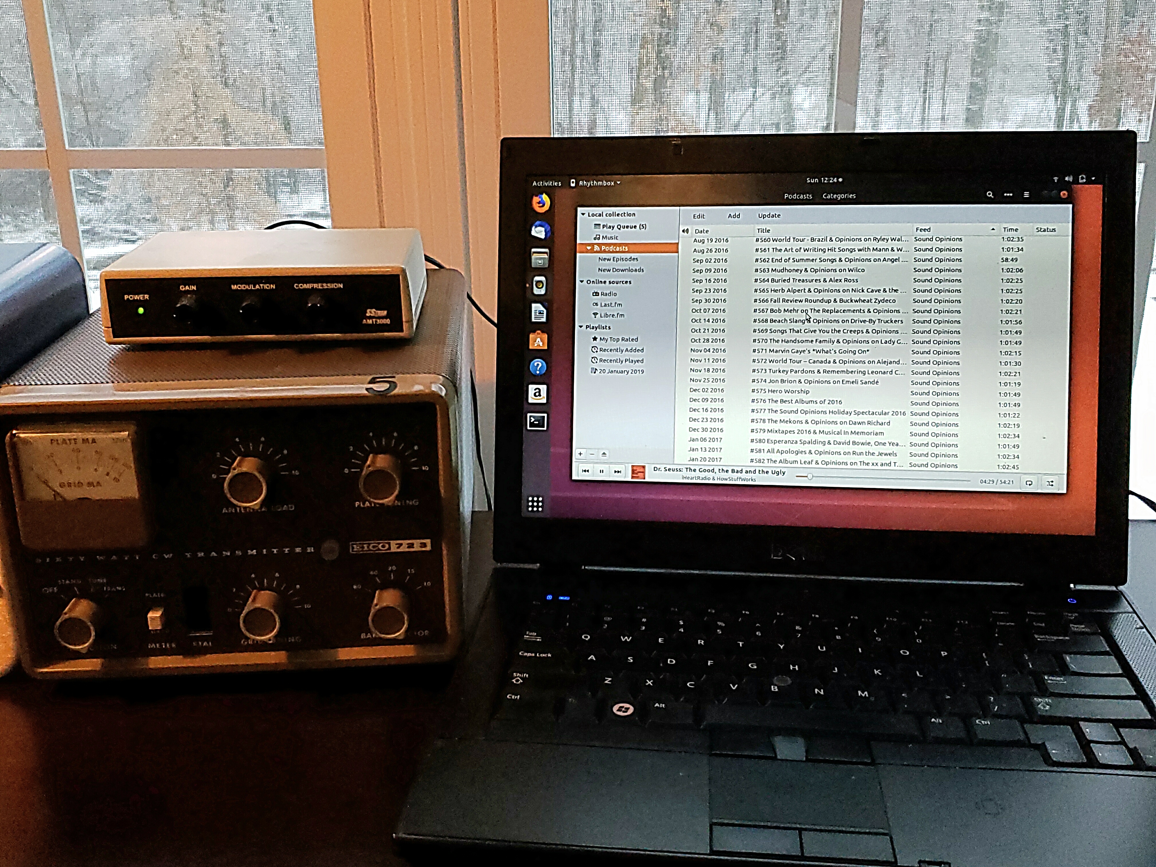
My transmitter is connected to a beater Dell laptop I bought refurbed from Walmart.com for a song.  I installed Ubuntu and use the Beatbox app to manage the queue of podcasts and MP3s.  I leave the station on 24/7 so now there is always something worth listening to on the radio.

I mentioned above that the AMT3000 has a compression control, which is a real nice touch.  Turning down the compression increases the hi fidelity of the signal, music actually sounds better to my ears than what is typically heard from commercial AM stations.

My home AM radio station – the SSTRAN AMT3000 transmitter sits atop my EICO 723 Novice transmitter on the AB1DQ operating bench. Programming is queued via the Beatbox app on my Ubuntu Dell laptop.

If you are looking for an AM transmitter to bring life back to your vintage radios, you won’t do any better than the SSTRAN AMT3000.  It is a real solid performer and simple enough build for anyone with moderate soldering skills.  I have gotten many years of satisfaction from mine.  Every December I use it to transmit holiday music to vintage radios placed throughout our house during our annual Christmas party – it’s a fine way to showcase the radios I have lovingly restored.

SSTRAN AMT3000 SPECS:

  • FCC Part 15 Compliant
  • Emission type: A3 Amplitude Modulation.
  • Modulation Type: Series Modulation.
  • Modulation Capability: 100%
  • Carrier Shift: less than 0.5%
  • Broadcast Frequency Range: 530 kHz to 1705 kHzin 10 kHz increments
    (a 9kHz increment version is also available for non-US radios)
  • Frequency Response: 10Hz to 20kHz
  • Audio Input Level: 200mV for 100% modulation
  • Audio Input Impedance: 4 ohms to 50K ohms
  • Distortion: 0.5%
  • Final DC Input Power: 100 milliwatts (full legallimit per FCC Part 15)
  • Duty Cycle: 100%
  • AC Ripple (Hum): Less than 0.3%.
  • Frequency Stability: 0.003%
  • Antenna Matching System: Pi-Network