

This past winter, my old high school buddy, who we shall call “Laurence” handed off to me his Zenith Model G724 radio, a nice 1950 Bakelite case table top AM/FM superhet. According to Larry, the radio played well but had a broken dial string.
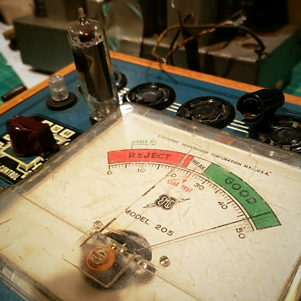
Dial strings can easily be replaced using common twine, and while I had the radio apart, it made good sense to replace the old wax and electrolytic capacitors and to test the tubes – simple basic maintenance to keep this radio working.
This radio has a selenium rectifier to convert AC to DC [Figure F, below]. While I was aware that selenium rectifiers are prone to failure as they age, I have never experienced a failure – most of the radios I have serviced feature tube rectifiers.
Laurence had shared my Facebook post about the service I had done to his radio on a vintage radio forum where an astute member spotted the selenium rectifier and asked if I planned to swap it out for a diode.
I decided I needed to broaden my knowledge of selenium rectifiers and what happens when they do fail. I came across two useful YouTube videos from two content providers I already subscribed to – Shango066 and All American Five Radio – that helped me fill my knowledge gap.
What I learned from both videos was that selenium rectifiers put out reduced voltage as they age, not delivering enough B+ voltage for the tubes. I also learned that if the selenium rectifier shorted out and overheated it would smell pretty awful and could cause more damage to the radio.
A modern general purpose rectifier diode, the 1N4007 can be used as a direct replacement for the selenium rectifier, however the selenium rectifier has a higher internal resistance than the 1N4007 which means a dropping resistor needs to be added in series with the diode to prevent tube filaments from burning out due to too much voltage.
In order to determine the value of the dropping resistor, I consulted the Sam’s Photofact and studied the schematic and voltage notes to find a reference voltage. According to my documentation, the grid voltage on pin 5 should be 125 VDC+.
Using jumper cables I placed the 1N4007 in circuit with my Heathkit Resistance Subsitution Box in series and my Voltmeter connected to pin 5 of the 35B5.
With the resistance set to 33 ohms, the voltage on pin 5 was 124.9 volts. [Figure A., below]
Because the resistance substitution box was old, I wanted to check the resistance with my ohm meter – I discovered that the 33 ohm setting actually read at 39.1 ohms. [Figure B., below]
I chose a 36 ohm 1 watt resistor from my parts box for substitution and when I tested it with the ohm meter and it read 38.0 ohms. [Figure C., below]

FIGURE A. 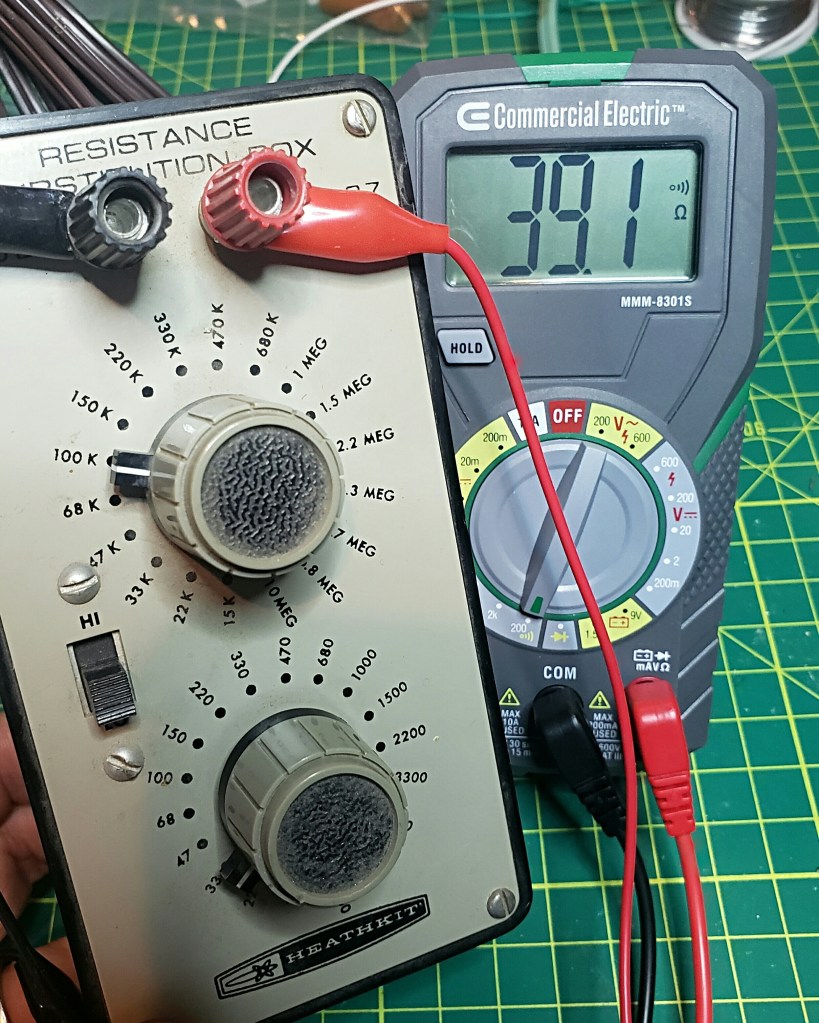
FIGURE B. 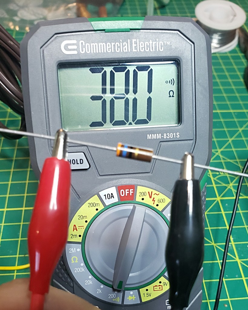
FIGURE C. 
FIGURE D. 
FIGURE E. 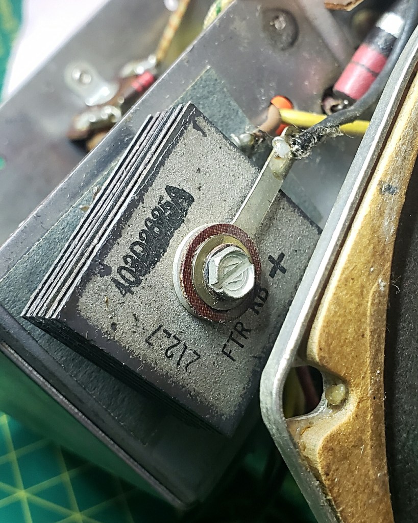
FIGURE F.
I soldered the 36 ohm resistor in series with the 1N4007 diode and soldered it into circuit. [Figure D., above]
I then tested the voltage on pin 5 of 35B5 and found the substitution worked fine as the voltage reading was now 128.8 VDC+. [Figure E., above]
In the end, Laurence gets a tuned up Zenith and the next time I see him, I shall collect my friends and family fee – 2 snorts of Jack Daniels Whisky! 🙂


Please leave your comments on this site, or drop me a line at James@ab1dq.com!
