

Material for this blog post was originally presented on the Meriden Amateur Radio Club Tech Net, on August 20, 2020, a 2 meter net held on the first & third Thursdays of the month on the W1KKF, 147.360+ MHz repeater in Wallingford, CT, and simulcast on Zoom.
My love of amateur radio goes all the way back to childhood when I would waste hours in my grandfather’s workshop in our basement building Radio Shack Science Fair kits and mucking around with all the dead radio and TV carcasses he accumulated. I have been melting solder for the better part of my life and to this day still love building kits and recapping, repairing and realigning vintage radios.
However, my skills have never been great… I lack what many employers have rudely called an “attention to detail.” All these years later, I’m sorry to say that still the majority of things I put together don’t initially work as they should.
I used to get discouraged but then realized this was actually a gift – – – instead of abandoning a non-functional project, which would make it a waste of my time and money, I have discovered the process of troubleshooting actually gives me more bang for the buck.
Troubleshooting requires a deeper dive in order to learn and understand how the circuit works which reinforces my electronics knowledge. Finding and fixing a malfunctioning piece of equipment is also very satisfying and rewarding – it’s like solving a puzzle, but in the end you get something you can actually use.
In this blog post, I’m going to cover some of the basics – including essential tools I use and the steps I take when tackling a new troubleshooting project.
Disclaimer – I am by no means an expert, I believe I’ve made that clear. What follows is intended to be foundational and inspirational to others who have been frustrated when troubleshooting electronic appliances. More advanced techniques dealing with specific circuits is beyond the scope of this post. Look for future posts dealing with more advance RF troubleshooting topics.
THE ESSENTIAL BENCH TOOLS
The most basic tools you will need for troubleshooting include:
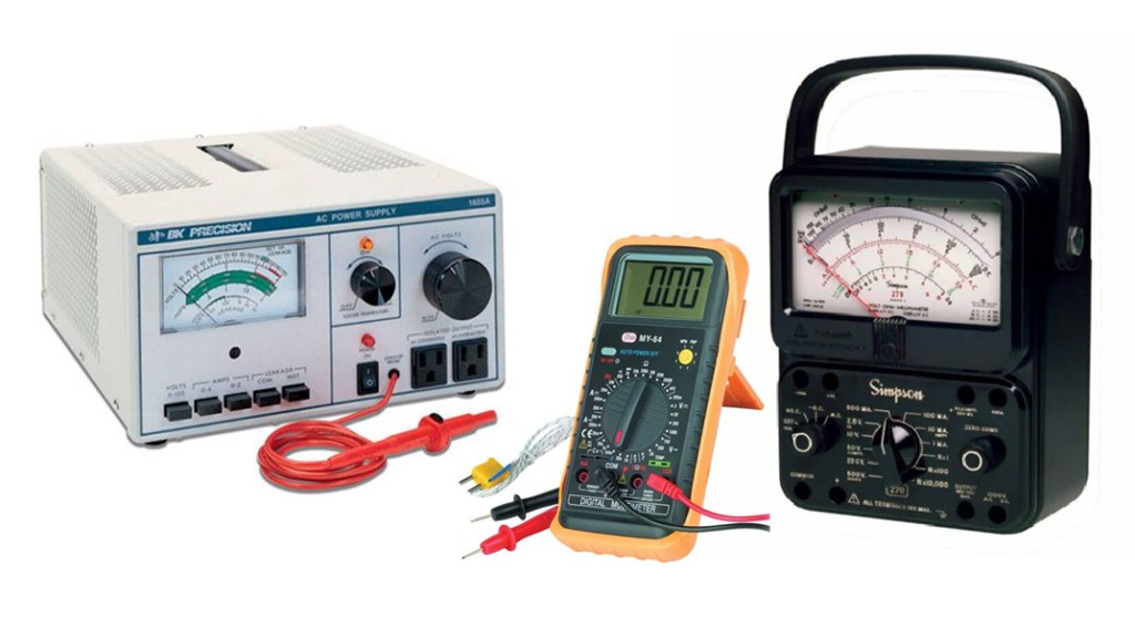
- A good stable bench power supply
You might be surprised the number of electronic problems are due to no or insufficient juice, reversed polarity and blown fuses. - A quality Volt-Ohm-Meter (multimeter) is essential for measuring voltages, current and resistance values. Today the majority of meters are digital and there are many serviceable units to be had for an inexpensive price.
A good workbench should have both digital and analog meters. Analog meters still have an edge over a digital meter in certain circumstances such as when reading fluctuating signals (current), as digital meters typically give you an average reading. This is an advantage when trying to peak a tunable circuit.

- Good magnification is essential for troubleshooting, especially when working with today’s miniscule parts and circuit boards with surface mount components. Either a good magnifying desk lamp, or a plug-and-play USB Microscope that plugs into your computer is going to be invaluable. Like very one else who has made it to middle age, I have experienced waning vision (which pretty much sucked since ever since I started wearing glasses at age 2), and dexterity. I got my magnifying desk lamp on Amazon and my USB microscope from QuickSilver Radio, a favorite source for ham radio cables, small parts and tools.
TECH TIP: In a pinch, your cell phone can be used to provide quick and dirty magnification. Simply use the camera to photograph the part you need to magnify then open the photo and zoom in – we are living in a Golden Age, my friends! - Temperature controlled soldering iron and tools. This is not an area to cut costs. Growing up I soldered with inexpensive solder irons from Radio Shack, seldom concerned with what their wattage ratings were – 15? 30? 45 watt? – Whatever it takes.
I have learned in recent years the importance of a good temperature controlled solder station as well as the importance of using the correct iron tip for the application. This upgrade has been a game changer improving the quality of my solder work, while reducing my stress and frustration.
It’s important to not use too much heat when working with delicate components and circuit boards, and it’s equally important to use too little heat when soldering joints.


TROUBLESHOOTING TIPS & TRICKS…. FIRST THINGS FIRST
The very first step in attempting to diagnose electronic equipment failure is to clearly define the problem., that is, what specifically is not working and also importantly, what else isn’t working?
Create a list of all symptoms and indicate whether the symptoms are intermittent. If intermittent, does the symptom occur when a specific control is activated? Does the problem stop if the appliance is moved or re-positioned? Once you have a list of symptoms and circumstances, evaluate the list – which symptoms might be linked? Where is there commonality to what is failing? Documenting and understanding all the symptoms can be useful.
The second thing to evaluate is the power situation. Technicians who do a lot of troubleshooting identify lack of power as the number one reason why a piece of equipment isn’t working. Sounds simple, but the question “Is the unit plugged in?” is foundational.
Make sure there is a fuse in the fuse holder, and that it isn’t blown. If it is blown, it will take more than just replacing the fuse, but you will know that something is awry with the power circuits – either a short or a failed component creating an overdraw of current.
Make sure that DC polarity is correct, and make sure there aren’t any broken power leads, disconnected power connectors, or cracks in the circuit board or broken traces around the power supply circuit.
After assessing the power supply, next up is an in depth visual inspection – this is where the magnifying tools come in handy. Carefully inspect both sides of the circuit board looking for obvious issues such as:
- Missing components
- Damaged/burnt out components
- Broken traces
- Cracked boards
- Signs of previous ‘work’
- Obvious mods, parts replacements
- Excess flux, solder blobs and cold joints

TIME FOR THE DEEPER DIVE
If your circuit is getting proper power and you didn’t find any obvious problems after a thorough visual inspection, it’s time for the deeper dive. This will involve gathering, reading and understanding all the circuit documentation you can get a hold of. This documentation includes:
- Schematic Diagrams
- Block Diagrams
- Chassis and Parts Layout
- Manufacturer Manuals and Supplements
- Third Party Manuals ( e.g. Riders, SAMS PhotoFact)
- Component Data Sheets
The internet makes so much information available to the troubleshooter, most of it free. These resources include You Tube and online forums. (QRZ, Yahoo, Google groups, RadioMuseum.org), various manufacturer websites, and instructional sites such as All About Circuits.

Don’t forget about local resources, namely your local amateur radio club where you will find numerous older and wizened “Elmers” who are generally happy to pass on their expertise.
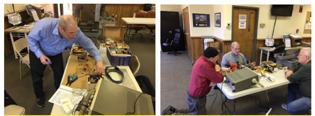
My local amateur radio club, The Meriden Amateur Radio Club here in Connecticut runs an open house every Saturday morning at the Wallingford EOC where we are headquartered. The open house features a repair bench staffed by the likes of NZ1J, Dave, KE1AU, Bob, and WB1GYZ, also Bob, who are always up for a new challenge.
WHAT’S CURRENTLY ON THE AB1DQ WORKBENCH?
(a troubleshooting case study currently in progress!)
Earlier this summer I constructed the MFJ 9340 40 meter QRP Cub Transceiver kit. This kit was not unlike many others I have built in the past including the WA3RNX 40 meter transceiver, and the Wilderness Radio SST 20 meter transceiver kit. The MFJ kit came with a circuit board pre-populated with all of the SMD components and required the builder to install the traditional through the hole parts.
Construction went smoothly over two or three evenings and I was happy to find that I had no ‘spare parts.’ (A good sign.) I was able to align the receiver easily per the directions in the construction manual, however when I attempted the transmitter alignment, I ran into trouble. What happened?

I started troubleshooting with a good visual inspection focusing particularly on the solder side of the board looking for bridged solder joints. Nothing looked suspect.
Because this was a kit radio, I had just about all the documentation I needed in the manual to start trouble shooting including the Block and Schematic Diagram, a diagram of component lay out, and a page of Troubleshooting Tips too.
I started with these diagrams and breaking the radio down into separate functions and began color-coding the schematic, block diagram and parts layout. This took a bit of time, and you could argue it wouldn’t be necessary for a simple transceiver, but doing so did provide me with a solid understanding of how the radio was designed and where I can set my focus for finding trouble….
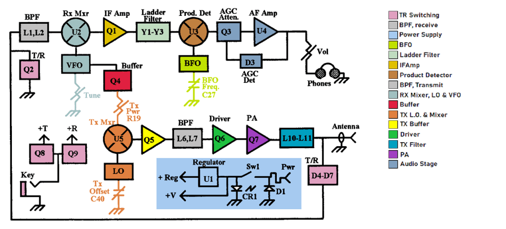

Alan, W2AEW, provides a fabulous walk through of the 9340 circuit on his YouTube channel, which contributed bigly to make short-work of my color-coding work.
So now I know where the sub-assemblies and their parts are located on the circuit board, and I can trace the stages of the circuitry on the schematic, great! Now I need to go even deeper to see if I can find where the problem is originating.
The MFJ documentation had a table of voltages for each of the transistors and ICs. I am always thrilled when I can find a voltage table like this or see that proper voltages are indicated on a schematic.
I created a simple Excel spreadsheet with the MFJ data and carefully measuring the test points on my radio, I was able to calculate unit and percentage variances which allowed me to find trouble spots.

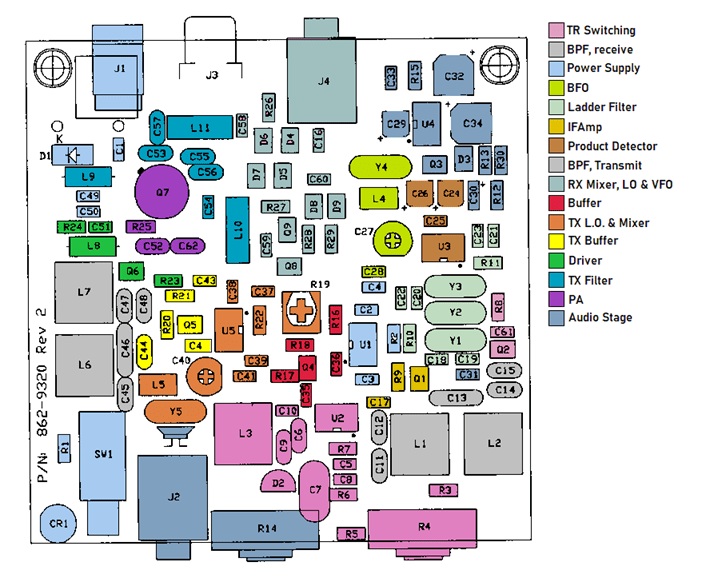
I quickly identified hat the biggest variances were found on Q6, the Transmitter Driver, U5 the Transmitter Oscillator chip and Q5 the Transmit buffer. None of that was a surprise since I knew my problem involved the TX function.
However, I also observed a sizable variance on the BFO buffer, Q4, which might be related…

[SLIDE 16] I marked the over/under voltage readings on my schematic and cross referenced the parts layout to determine where I needed to focus. These parts were pre-installed, so I worked backwards from each in the circuit to look closer for problems.

WHAT’S NEXT AND SOME KEY TAKEAWAYS
This may seem like a strange place to end a blog post, but as of the time this material was presented on the MARC Tech Net on August 20, 2020, I had not yet finished my troubleshooting work on the MFJ Cub.
Next steps on the project will be to trace back ‘upstream’ from the variances on the schematic and closely examine my work, verifying that I placed the proper components where they belonged, and that my solder joints are good – not cold, and not blobby and bridged. I also want to take a close look on the two torrid inductors in the TX filter, L10 and L11.
While I had hoped and planned to have completed my work on the Cub prior to the net, I was unable to, and that’s my final lesson for now.
When troubleshooting, don’t rush and don’t get aggravated. Take it slow, work methodically and logically. Never jump to conclusions at the first sign of something unusual too. Many times the problem isn’t obvious and many times too, it’s not complicated. Stick to it and in the end you will find yourself rewarded with a satisfied sense of accomplishment.
As for me, I will update my blog when I have discovered and resolved the problem with the MFJ 9340. Watch for that post, or feel free to shoot me an email if you have questions, suggestions or want to discuss further.
GENERAL TROUBLESHOOTING TIPS
I mentioned that this material was originally presented during a 2 meter net. I want to thank the following stations who checked into the net, and I will close with some bulleted advise, tips and tricks that were shared by the participants…
STATIONS PARTICIPATING IN THE 2M NET:
W1EDX, N1ZN, K1RCT, KC1KQH, N1LES, N1KGY, N1AKN, N1GNV, N1BRL, K1LHO, K1JKF, KC1LGA, WB1GYZ, KE1AU, W1DQ, W1YSM
SOME COLLECTIVE WISDOM:
- When testing a circuit, be careful with the test probes so you don’t create shorts. (N1ZN)
- Keep your focus simple, look for the low hanging fruit. (K1RCT)
- The problem is usually something basic and straightforward, and will more often then not involve the power supply (N1GNV)
- Use the proper equipment when troubleshooting – you can easily destroy a circuit by using too powerful of a heat gun, or solder iron. (N1LES)
- Proper calibration of test equipment is essential. (N1KGY)
- High spec. test equipment with proper test ranges is important to have (N1AKN)
- Google can be an outstanding resource for just about anything technological from cars to electronics. (N1AKN)
- When working with an old dusty chassis, take it out to the garage and reverse the shop vac to give the gear a good blow-out. (N1BRL)
- Be aware of high voltages and take proper precautions including shorting out capacitors before poking around. (KE1AU)
- Work slowly, methodically and logically. Don’t expect a quick resolution and don’t set false deadlines to complete your work. (AB1DQ)
©2020 AB1DQ, James M. Surprenant and all others as cited.
