This weekend I returned to a shelved project from several months ago, a complete 40 M QRP station built around the Easy Transmitter & Easy Receiver kit line from Pacific Antenna (QRPKits.com).
The CEID is a nicely equipped maker space at Yale and their Wednesday Workshop series allows students, faculty and staff to learn something new by making. Popular Wednesday Workshops have included chocolate making, woodworking, 3D printing and W1YU would program a workshop to introduce the uninitiated into radio fundamentals.
We chose the QRPKits.com 40-meter direct conversion receiver for one of our workshops because the kit was simple to build and able to be completed in less than two hours, was inexpensive, and had a reputation of working the first time. That night 20 CEID members, most of whom never soldered before, paired off into 10 teams and after a presentation on RF and a brief soldering tutorial, they got down to work. I’m very pleased to say that out of 10 kits attempted, all 10 worked, with only a couple needing nothing more than a touch up of a cold solder joint or two.
My Current Project
My initial plan was to build the Easy Receiver and Transmitter and mount them into a single enclosure (a cigar box) to make an all-in-one station. In addition to the receiver and transmitter, I had also planned to incorporate the Easy Audio Bandpass Filter, the Easy TR switch, and the Easy Low Pass Filter to limit out-of-band harmonics on transmit.
I had assembled all of the basic kits several months ago and as I often do, became sidetracked and never finished the project. I came across my circuit boards recently in my basement workshop and decided to pick up from where I left off.
I had previously completed the receiver, audio filter, TR switch and the low pass filter. The transmitter was still in its original packing, so this became my first project for the new year.
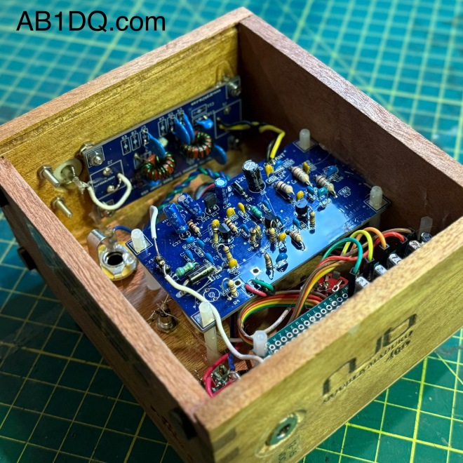
My completed 40M transmitter with rotary crystal selector and fine tune control. The completed project delivers 2.0 watts on all five frequencies.
A Couple of Modifications
I mentioned I came across the unfinished project in my basement recently. Over the past several months I have been working on organizing my workspace including inventorying and sorting the myriads of components I’ve managed to stockpile over the years. One of the things discovered in doing so was a variety packet of 40 and 80-meter HC-18U crystals for the QRP experimenter.
I decided I wanted to modify my transmitter build so instead of just being limited to the 7.040 crystal that came with the kit, I could easily select a different frequency by swapping crystals. The kit itself makes a provision as it includes a socket so the builder/operator could plug in a different crystal if they wanted to change frequencies.
My modification takes the concept a step further. Creating a small bus board on which I mounted several crystals and connecting one end to a rotary switch, I was able to make changing frequency as easy as twisting a dial. My transmitter allows the operator to quickly choose between 7.030, 7.040, 7.055, 7.110 or 7.118 MHz.
I made two other minor modifications. I incorporated the low-pass filter on board in the transmitter cabinet instead of as a stand-alone accessory, and I also added a yellow LED coupled with a 1K resistor to provide a power on pilot light on the front panel.
The green PCB is my multi-crystal mod. One side of the crystals are tied together and connected to the crystal socket on the main board while a ribbon cable connects the other sides to the rotary switch below.
I used a small Nub cigar box for my cabinet. I sanded off some printing on the bottom surface and applied a nice cherry stain to the box. Orienting the box so I used the thin bottom as the front of the radio, I had no problem with short potentiometer shafts. The sides of the box were quite a bit thicker, however, and I needed to countersink the holes drilled for the SO239 antenna connector and the coaxial DC power socket.
Another nice feature of the Nub box is that it has a slide off lid, which now becomes the back panel of the radio. It makes for easy opening for repairs or adjustments – or for show and tell at the local club.
How does it work?
The Easy Transmitter Kit promises 2 to 2.5 watts output on the 40-meter band, and I am very pleased to report that indeed, I measured a solid 2.0 watts on all five frequencies. The circuit includes a 5K potentiometer for fine tuning which allows a band spread of a few kHz. For the four lowest frequencies, I spotted my signal right on frequency with the fine tune knob set dead center. 7.118 was a bit off center, unlike the others, but still solidly within range of the fine tune control.
Needless to say, I was very impressed with the initial performance of the transmitter the first time I powered it up.
What’s Next?
I mentioned that I have already purchased and assembled the other kits in the QRPKits.com “Easy” line. I plan on mounting the 40 meter Easy Receiver and the Easy Bandpass Filter in two separate but matching Nub cigar boxes. I plan to mount a speaker in bandpass filter cabinet and include a headphone jack, and to not include any speaker on the receiver. I plan to either use the receiver with earphones (my preferred means for operating CW) or will use a 3.5mm jumper to feed the bandpass filter/speaker unit.
I am contemplating building a small linear amplifier to give myself a boost as needed. QRPKits.com and QRP-Labs.com each offer a simple RF amplifier at a low price that promise to boost 2 watts into the 7-10 watts out range.
I highly recommend the QRPKits.com Easy series of kits for the aspiring kit builder or the old timer, like me. As priced, they remain a great value, and the kits are easy to assemble and best of all – have always worked as advertised.
I plan to blog about the matching receiver and audio amp/bandpass filter as I manage to complete those projects. Have you built any of the QRPKits.com kits? What was your experience? Drop me a line and let me know how you fared at james@ab1dq.com.
Thanks for stopping by my blog & 73!
A peak inside – the auxiliary low pass filter was mounted to the side just above the S0239 connector, using a mounting screw from the S0239 and a modest amount of hot glue to hold the board in place.
One of the best things about autumn is that after the pretty leaf-peeping season ends early in the month, there are several weeks of pleasant enough weather and the lack of leaves makes launching wires into tree branches so much easier. Thus, for many hams like myself, installing new antennas and repairing damaged existing ones is as much a fall tradition as football and pumpkin spice.
Last Spring I attempted to install an End Fed Half Wave Antenna cut for 40 – 10 meters running from the window of my 2nd floor shack across the yard and terminating in the upper branches of a dead tree on the edge of the backyard.
Building the simple antenna was a piece of cake. I built the HFKits 49:1 EFHW transformer kit (also available from the ARRL) and cut a 66 foot piece of wire (roughly half the wavelength of the 40-meter band.
However, I failed spectacularly in attempting to get a line up into tree. I had been using a pistol crossbow with an attached spinning reel but despite all of my best attempts I could not place the line where I wanted it.
Losing my race against time as the spring foliage began coming in, I opted instead to orient the antenna with a downward slope to a terminal point about 15′ up to the base of a tree bordering the woods.
The antenna worked – I mean we all know EVERYTHING resonates – but it was a disappointment. The antenna also lacked a choke and was very noisy. I was also remiss that I couldn’t operate on 80 meters.
So, the summer of 2024 passed. It was a good summer in many ways, but I didn’t operate much from the home QTH. I enjoyed several POTA activations and set my sights on the fall antenna season to improve my EFHW.
When September rolled around I spent several weeks watching dozens of YouTube videos and reading articles on constructing a shortened end-fed half-wave antenna that would resonate on a portion of the 80M band and resolved to properly erect the improved antenna.
NOV. 2: CHOOSING A DESIGN & WINDING THE INDUCTOR
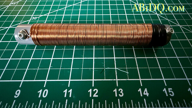
In researching EFHW physics and construction, I found VK4YE’s YouTube presentation on his 5-band EFHW which resonates over a narrow swatch (@ 100 kHz) of the 80mb by including a loading coil trap. I found similar plans on several other websites but most called for a 110 uH trap. VK4YE’s design called for a 70uH inductor. Appreciating his comprehensive and thorough description of the design, I decided to work directly from his plans and began gathering my materials.
The directions call for 120 turns of 1mm magnet wire on a 25mm coil form. I am that strange fellow who actually enjoys winding coils, don’t ask me why. I’m pleased with my work – I measured the coil and found it to be right around 70 uH. My only failure was that I cut the PVC ever so short before making the windings (see photo). However, I believe it will work fine, and the coil will be shrink-wrapped before being hoisted up.
NOV. 4: TESTING THE TRANSFORMER & CUTTING WIRE
Today I completed construction of the antenna itself. Winding the coil was the most involved step and all that remained was to cut the wire lengths to spec and attach it to the inductor using a pair of dogbone insulators for strain relief.
I also tested my 49:1 transformer tonight to confirm that it is functional and that the impedance is correct.
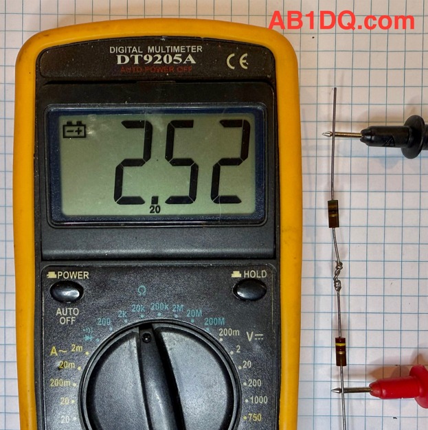
I placed a 2.5K resistor load across the output and ground and used my RigExpert antenna analyzer to read SWR which was consistent at about 1.5 or less across all bands from 80 to 10M.
NOV. 9: TUNING THE ANTENNA
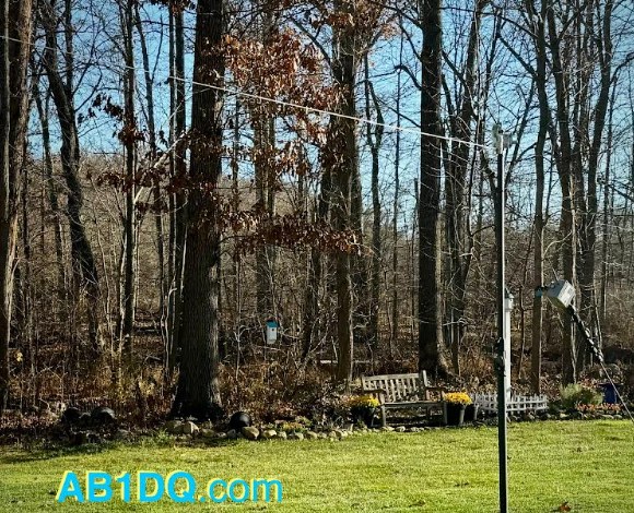
Taking advantage of another great weather Saturday, I strung up the end-fed antenna in the backyard to tune it up today.
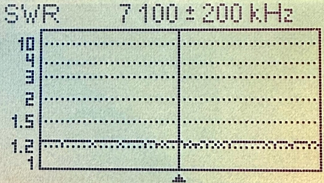
I was very pleased to see SWR readings of 1.5:1 or less on all bands except 80M, which was to be expected. All the documentation I researched about the 80-10m EFHW design stated that while the loading coil allows for resonance on 80 meters, only a narrow portion of the band will tune with a low SWR and it is essential to choose which portion of the band you want to resonate.
As I prefer operating CW on HF, I aimed for the lower portion of 80 and I found shortening the “C” segment of the antenna by 12″ brought the SWR down to less than 2:1 on the CW portion of the 80-meter band. See my SWR readings before and after trimming the antenna in the table below. The segment lengths are in inches.
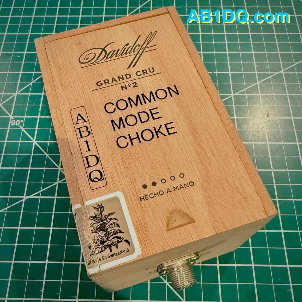
NOV. 10: CONSTRUCTING A COMMON MODE CHOKE
On November 10, I built the final component of my new EFHW antenna, a Common Mode Choke, or CMC. It is highly recommended that a choke be used with an end-fed antenna to prevent the shield of the coax feedline from becoming part of the antenna system and radiating RF unintentionally.
I built my choke by winding four turns of RG-8x coax through 10 ferrite toroids and mounting the works inside a small Davidoff cigar box with an SO239 connector on each end. The choke will be placed where the antenna feedline enters the house.
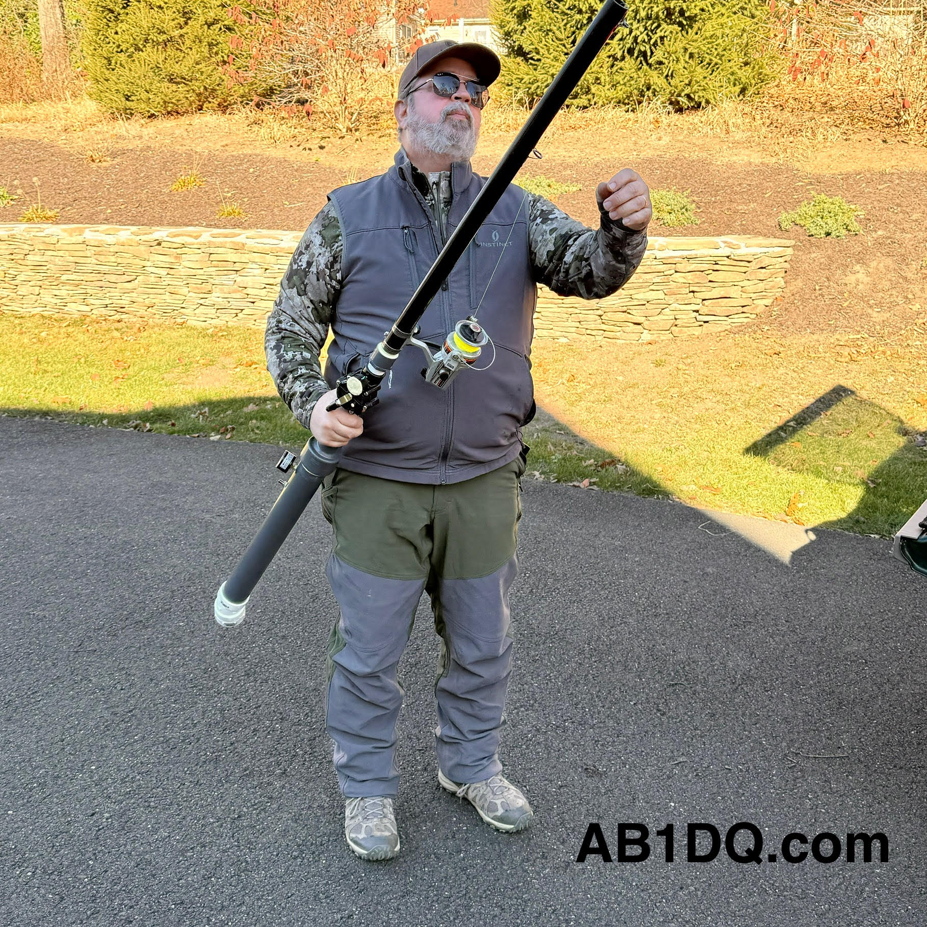
This past Saturday, November 16 brought more mild weather, and as our usual Saturday morning club open house was canceled that day due to a scheduling conflict at the OEM, it made it possible for me to get with Rob, K1RCT, our club’s station manage and an all-around good guy, who brought his mighty spud gun to my QTH to help me complete the installation of the antenna.
I always enjoy Rob’s company and his willingness to share his radio expertise. Years ago, our former club president, Bill W1KKF/SK made a couple of trips out here to Cheshire with his bow and arrow to help me string wires in the trees. I was always grateful to Bill for his help and his presence is missed by all who knew him. But now, Rob has brought antenna launching to a whole new level with his spud gun.
Prior to Rob’s arrival, I had tied off the feed point end of the antenna. A short run of coax extends from my transceiver to the Common Mode Choke placed on the windowsill of my 2nd floor shack.
A 3′ coax jumper connects the CMC to the 49:1 un-un on the other side of the window. I used a pool noodle as a pass-through. I drilled a small diameter hole matching the size of the jumper, and then using a razor blade, made a slit extending from each hole to allow me to feed the cable with the PL-259 through. The pool noodle makes for an inexpensive, easy and insulated feedline pass through.
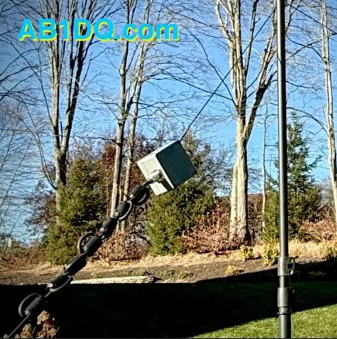
The antenna then begins from the top lug on the un-un, extending a few feet to a dogbone inserted for strain relief. A short length of rope is tied off to the eyelet on the top of the un-un and is passed through a galvanized steel eye hook attached adjacent to the top of the window pane.
Here are a few final photos of the end of the antenna raising.
NOV. 17: ON THE AIR
My timing to complete the antenna project couldn’t have been better as this past weekend was the ARRL November Phone Sweeps – my favorite contest (as a non-contester). In years past, my goal for both the CW & Phone Sweeps was to beat my score from the prior year.
I am happy to report that I made 60 contest contacts, operating at my leisurely pace for a couple of hours. I searched and pounced and was able to work nearly every station I called on 40, 20, and 15 meters. The map seems to suggest the antenna performs as intended…
Did you have a fall antenna project? Have you used an end-fed half-wave antenna and what is your impression of the design? Leave a comment or drop me an email at james@ab1dq.com and let me know what you think.
I was thrilled to see that the good folks at the Four State QRP Group released the 4th revision of their popular Bayou Jumper 40M CW Transceiver designed by Jim Giammanco N51B and David Cripe NM0S last year.
The Bayou Jumper, first released in 2017, is a 40M QRP transceiver that is an homage to the classic Paraset, the legendary transmitter/receiver supplied to the resistance groups in France, Belgium and the Netherlands during World War II.
Whaddon Mk VII – Paraset Clandestine Transceiver c. 1942
The Bayou Jumper, an updated solid state CW only radio kit is intended to be fitted into a hinged wooden suitcase style box available from Hobby Lobby or any other similarly sized box.
Given my recent obsession with building QRP radios and accessories into empty cigar boxes, I felt the Bayou Jumper would make an excellent candidate for cigar box treatment. I found a gorgeous Perdomo 20th Anniversary cigar box in my stash that was approximately the right size, featured gorgeous red and gold artwork on a black background and was constructed of heavier wood than many of the other cigar boxes in my collection.
The Bayou Jumper front panel was a perfect flush fit left to right in the Perdomo box, and only fell 1/2″ short front to back. I modified the box by gluing a 1/2″ square dowel along the top hinged edge to fill the empty space.
Other mods I made to the cigar box included:
Adding weights to the bottom of the box to prevent the radio from tipping over backward when the lid was up and to provide a little more heft,
Adding a pair of latches to be able to secure the lid closed, and,
Reinforcing the original pressed in hinges with three supplemental screw-in hinges.
Building the Kit
I chose the Bayou Jumper to be my 2022 Christmas project. Professionally I have worked in an administrative role in higher ed for the past two decades and one of the biggest perks of working at most leading universities is they completely shut down for an extended winter recess. Building an electronic kit during my winter recess takes me back to my teenage years when I’d spend my holiday break from school constructing the electronic kits I received as Christmas gifts.
Like every NM05 designed 4SQRP kit I have previously built (the Murania One Transistors Boy’s Radio, the 4S-QRP Antenna Tuner, and the Ozark Patrol Regen Shortwave Receiver), assembly was a relaxing no-stress experience. Once again, I was very pleased with the high quality of the double sided etched-through printed circuit board, the quality of the electronic components and hardware, and the in-depth and easy-to-understand instructions and documentation.
I encountered only two minor issues in building the Bayou Jumper Revision D that were hardly a problem, barely an inconvenience.
The first was a missing resistor, R15, a 1/4 watt 100K ohm resistor. I have never experienced a missing part when building a 4SQRP kit and it’s probably just as likely I dropped or lost the resistor than it was wasn’t shipped in the kit. Regardless, I had the correct value resistor on hand in my home stock supply.
The second matter involved the jumper wires provided to supply current to the multi-color LED on the front panel from the main PCB. The instructions stated the kit included a 12″ jumper wire with header pins included in the kit that needed to be cut in half to make two jumpers. However, the jumper wire included in my kit was only 5.5″ long and once cut it in half as the instructions directed, one of the resulting leads was too short to mate to the header pin on the PCB.
As with the missing resistor, I had plenty of jumper wires that I use for breadboard prototyping on hand and was able to create the necessary jumper wires with sufficient slack to reach the contact points.
All in all, the kit went together in just 3 days’ time as I prefer to work slowly and methodically whenever I build a kit. (Whenever I rush through a project I typically find that any time I saved working quickly would be lost in extensive time consuming trouble-shooting that would be needed!)
The topside of my populated PCB. Assembling the kit was straightforward and fun.
Winding the Transformer
The Bayou Jumper features three inductors etched into the PCB but still requires the winding of a single transformer on a T 6-7 toroid core. I have never found winding coils to be difficult or stressful, and in fact, I generally enjoy it especially when the kitter provides excellent directions and illustrations, which 4SQRP did.
The transformer required 3 windings, one of 19 turns, one of 4, and the last of 2. The completed transformer can be soldered to either the top or bottom side of the PCB, based on the builder’s preference and tje screen printing on the circuit board makes installing the completed transformer essentially foolproof. I chose to mount the transformer to the bottom side of the board to make it easily accessible for adjusting the spacing of the winding to adjust the receiver’s tuning range.
The completed transformer mounted to the bottom side of the PCB.
Faux Crystals?
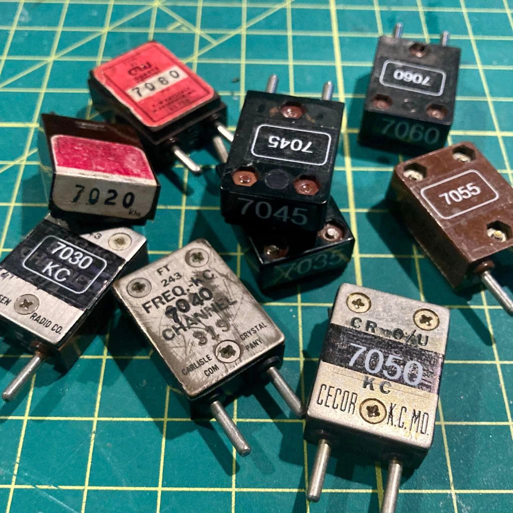
The Bayou Jumper’s crystal socket accepts the classic FT-243 crystal form, a popular Cold War era crystal size that today is no longer manufactured and increasingly rare.
The Bayou Jumper comes supplied with a pair of HC-49 crystals for 7.030 and 7.122 MHz, and two crystal adapter boards to fit the HC-49 crystals into the FT-243 sockets.
Vintage FT-243 cases are large enough to accommodate modern small HC-49 crystals and with its 3 screws, the FT-243 can be easily opened and re-sealed, making it possible to re-stuff FT-243 cases for modern QRP use.
Using several of the FT-243 crystals for non-amateur frequencies that I picked up at ham-fests, I have modified 9 crystals for use on the 40 meter CW sub band, all ready to go in my Bayou Jumper.
Receiver Alignment and Final Assembly
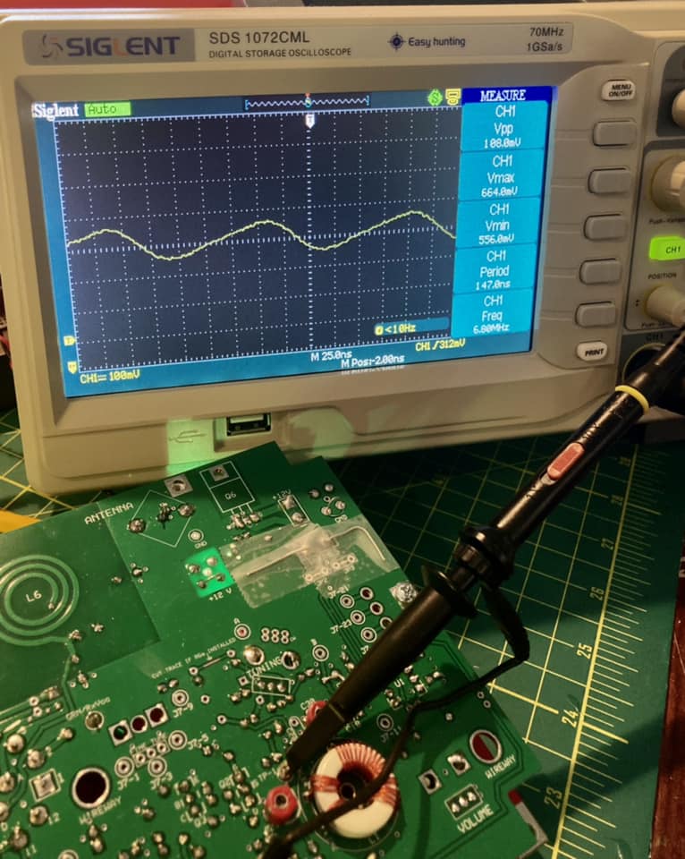
Again, the excellent directions made aligning the receiver a snap. Instructions are provided for a variety of alignment methods using an oscilloscope, a frequency generator or a calibrated receiver capable of CW reception. Having all three available to me, I tried all three methods and was pleased when all three were in sync.
I started taking a frequency reading with the tuning dial set to the low end of the scale with my O-scope and read 6.897 MHz.
Next I tried sweeping the dial of my frequency counter to spot the point where oscillation could be heard in the earphones. My frequency counter has an analogue scale and was able to read the resonant frequency at about 6.9 MHz.
Finally I set my portable C. Crane Skywave SSB travel radio for LSB and tuned to the 6.900 and tuning up and down was able to hear the receiver’s oscillator at about 6.895 MHz.
Following the directions to adjust the tuning range by spacing the L1 windings on the transformer closer together or further apart and then adjusting the C30 trimmer, I was able to achieve a final tuning range of 7.000 – 7.167 MHz which should be more than adequate for the CW sub-band I would use.
Finally, I followed the directions to verify regeneration and was happy to find that my receiver needed no further adjustment. Satisfied with my work, I mounted the radio in the cigar box and am looking forward to putting my Bayou Jumper on the air.
Stay tuned for Part II where I will report on my experience operating the Bayou Jumper on the air and any future adjustments or modifications.
This August I picked up a pair of Heathkit HD-16 Code Practice Oscillators for $10 at the flea market at the ARRL New England HamXposition in Marlboro, Massachusetts. The CPOs were tech-specials, non-functional, but ‘mostly there’ with only a few missing parts.
BEFORE: What $10 will buy you at a ham radio flea market.
The HD-16 was Heathkit’s second code practice oscillator, introduced in 1974 and following the first Heath CPO, the CO-1 which was first sold in 1959. The HD-16 was sold until 1974, replaced by the HD-1416 in 1975 which sold with a few cosmetic variations until 1990.
Up until the turn of the century, prospective hams needed to demonstrate the ability to copy and send Morse Code at 5 words per minute (WPM) along with passing the written practical exam to earn the entry level Novice Class license. Advancing to higher class license classes required the upgrading ham to demonstrate the ability to send and receive code at faster speeds – 13 WPM for the General license and 20 WPM for the Amateur Extra Class.
In 1999 the FCC eliminated the 13 and 20 WPM upgrade exam requirements requiring hams to only demonstrate an ability to send and receive code at 5 WPM for high frequency privileges. Then, in 2006, the FCC eliminated all Morse Code testing altogether in accordance with the worldwide policy change the International Telecommunication Union made in 2003,authorizing each member country to determine whether or not to require individuals to demonstrate Morse code proficiency for licensing.
Despite the fact that hams no longer have to demonstrate the ability to copy and send Morse Code, operating CW or Continuous Wave with code remains as popular as ever in amateur radio. Many hams today choose to learn the code and many of us (yours truly included – a ham who only needed to pass a 5 WPM exam back in 2002), very much enjoy ‘pounding brass.’
Thus, the code practice oscillator, or CPO for short, was and remains a very useful piece of equipment for any ham aspiring ham to operate using Morse Code.
My Restoration Project
I began by disassembling both units completely and saving the screws, nuts and other hardware in (what else?) a cigar box in order not to lose any original parts.
The guts of both CPOs liberated from their cabinets.
I washed the cabinet parts in warm water and dish soap and gently scrubbed away at the stains with a soft brush. The back halves of both cabinets were scuffed and scratched badly so I chose to re-paint them in flat black.
Purists would only use the signature Heathkit dark green paint, but I didn’t have any on hand and, while I appreciate complete restorations of antiques, my philosophy for repairing old radio gear has always been to take advantage of what is available to make the vintage equipment usable to me today.
After sanding the enclosure backs with a fine grit sandpaper I applied 3 thin coats of flat black paint and then coated all pieces with 2 coats of clear coat. To compliment the blacked out cabinet sides, I also painted the speaker grilles with flat black paint and replaced the enclosure screws with new black screws.
On to the electronics
I found the original HD-16 manual online and printed a copy for reference. Like all Heathkit manuals, the HD-16’s was well written and included the schematic, complete specs, and some nice content on circuit theory and Morse Code.
Heahtkit HD-16 schematic from the original manual.
Circuit theory
From the original Heath manual…
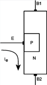
The unijunction transistor, Q1, is a special type of semi-conductor device, with two bases and one emitter, which acts as a relaxation oscillator in the following manner: When the key is closed, capacitor C2 is charged by the battery voltage through resistor R1 and the Tone control until the Emitter (E) voltage reaches the point at which the Emitter is forward biased with respect to B2.
Emitter current then flows because the dynamic resistance between the the Emitter and base one (B1) then drops to a low value. R2 drops the battery voltage to a low level, permitting C1 to charge to a higher voltage than B2.
Capacitor C1 discharges through the Emitter and Volume control until the voltage at the Emitter drops to the point where the Emitter is no longer biased. The cycle then repeats itself at a rate governed by the setting of the Tone control.
The pulsating base current, or oscillator signal, is developed across the Volume control. From the arm of the Volume control, the signal is coupled through the normally closed contacts of the phones jack to the speaker.
The lamp circuit uses the key as a switch that makes and breaks the C cell battery voltage to the lamp.
On Unijunction Transistors
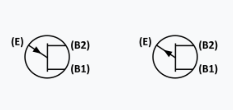
When I first glanced at the HD-16 schematic, I didn’t notice that the transistor was neither a familiar BJT or a FET. Upon closer study I noticed that Q1 is a “unijunction” transistor and was labeled with two bases, B1 & B2 and an Emitter, E.
Schematic symbols for the UJT: N-type on left, P-type on right
My immediate concerns were how rare the 4JX5E670 is, and whether they or a solid equivalent can be found at a fair price today should I need to replace them. My concerns were tempered however by the excitement that this project is going to afford me the opportunity to learn something new.
Up to this point in my life, I have had a cursory knowledge of transistors. I knew the difference between NPN and PNP Bipolar Junction Transistors – their construction and function – and I had a very basic understanding of how a Field Effect Transistor differed from a BJT.
Doing a little Googling, I learned that UJTs could only function as a switch and not as an amplifier. This made sense as the ability to generate pulses would be key to function as an oscillator at the heart of the HD-16.
Structure of a P-type UJT (source: Wikipedia)
Back to the project… assessing the damage.
At first glance, one HD-16 was missing its lamp and the C cell battery holder. The C cell battery holder in the other HD-16 was extremely corroded. Also missing were three of the four 9 volt snaps. One of the 10K tone potentiometers was gunked up and the shaft would not turn. Otherwise, everything else appeared to be present…. not bad.
I grabbed a 10K pot from my on hand parts stock and replaced the seized control and I soaked the other pots as well as the switches with de-oxit and worked the contacts.
I decided to replace the 0.22 uF capacitors with a pair of new Mylar caps from my stock. I did not test the fixed resistors and I didn’t even bother to check to see whether I had any 4JX5E670 UJTs in my parts supply. I would dive deeper and replace any of these parts if the oscillators failed after the other work I did.
I debated whether to replace the lamps with LEDs, a popular and logical mod. Doing so meant I could eliminate the 1.5 volt batteries altogether and complete the mod by adding a dropping resistor from the 9V batteries and rewiring the SPDT switch.
I liked the way the original incandescent dial lamp looked so I didn’t do a mod for LEDs. Since I needed to replace one of the missing C cell holders and the remaining one was badly corroded, I replaced both with modern plastic holders. I attached the new holders to the inside of the cabinets using 3M 2 sided tape.
I was unable to determine whether the HD-16 was a DIY kit or was sold only as a completed unit as I couldn’t find a construction manual online. So I took the time to sketch out the schematic and trace the parts layout creating a pictorial diagram I could use to confirm the circuit was complete.
Putting it all together
I worked on both oscillators side by side, working through each step of the restorations on one unit, then the other. It made sense to work this way as I could stay focused on each step as I worked.
After completing the parts replacement I grabbed some batteries and tested each HD-16 before attempting reassembling. Fingers crossed, both worked fine and I was relieved I didn’t have to address replacing the unobtainium transistors.
One of the completed electronic restorations – ready for testing and reassembly.
Reassembly went smoothly. I started by replacing the lamp grommet and inserting the lamps into their holes on the top of the enclosures and then installing the speakers and grilles.
Next I reattached the springs on the backs of the cabinets – this was Heathkit’s clever idea to secure the 9 volt batteries securely in place – and I stuck the new C cell holders onto the back of the enclosure using 3M double sided tape.
Next I installed the switches, confirming that they were properly oriented to light the lamp when set to “LIGHT,” and then I re-inserted the two potentiometers and the key and phones jacks to the front panel.
The last thing I did before closing up the cabinet was to secure the terminal strip to one of the speaker screws. The space available was tight, but not impossible. I took special care to make sure that the transistor and other component leads weren’t shorting out against each other. I did another test of both units before closing up the cabinets.
Both HD-16 cabinets ‘re-stuffed’ and ready for buttoning up.
Finishing touches
Both HD-16s had the original metal foil serial number sticker stuck inside the cabinets, but they were in bad shape and not salvageable. So I created a “new-retro” style serial number sticker for each unit in order to preserve each CPO’s history.
AFTER: Two restored Heathkit HD-16 Code Oscillators ready for use!
Do you or did you have a Heathkit Code Practice Oscillator? If so, which model and how did you like it? Comments and questions encouraged. Drop me a line at james@ab1dq.com to join the conversation!
One of the most formative experiences that launched me on my radio path occurred when I was about 11 years old and in junior high.
I was already in love with electronics and radio having built several simple Radio Shack kits and having spent countless hours in my grandfather’s radio workshop in our basement, devouring his stash of vintage Pop Electronics and DeVry home radio & TV repair coursebooks.
I recall that at the time, the annual school science fair was coming up and I was preparing to do my project on the world of electronics.
In those days, my dad shared an office at work with a coworker who was a ham radio operator. His name was Frank Pariseau, W1AQO, now a silent key. My dad was into the citizen band scene of the late 70s, and he would often tell me stories of how Frank would constantly try to entice him to getting his ham radio license.
One often repeated story was about the day my dad came into the office one morning to find two pieces of masking tape, a short piece followed by a long piece stuck to the wall.
Frank asked dad what that was, and dad replied, “masking tape.”
“No, no, no, Jim,’ Frank exclaimed, “that’s the letter ‘A’ – di-dah, that’s Morse Code! You now know your first character!”
“No Frank, that’s graffiti, you should take it down.”
Despite Frank’s best efforts (and mine in dad’s years), the old man would never get his ham radio license.
However, while Frank may have failed to convince my dad to get on the ham bands, he would probably have been pleased to know, that although I never had the opportunity to meeting him, I acknowledge and give thanks for Frank’s inspired act of generosity he made to me that fall that planted the seed that firmly set me on the path of a rewarding lifetime hobby in radio.
One night my dad came home from work with a surprise under his arm. He was carrying a vintage Hallicrafters S38 general coverage receiver that Frank sent him home with for me to try out.
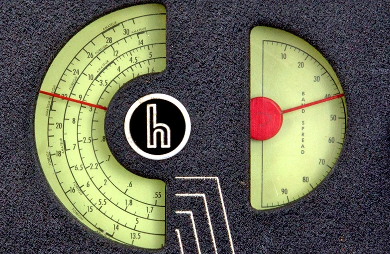
The radio was a delight for me to behold. I marveled at the beautiful dual tuning dials – the left with its four nested scales with more numbers than I’ve ever seen on a radio, and the one to the right that in sharp contrast had a single scale simply marked from 00 – 100.
Each dial had its own massive tuning knob next to it and there were other knobs and switches with labels I’ve never seen on any other radio – “AM/CW,” “CW PITCH,” “RECEIVE/STANDBY.” And the brand name, “the Hallicrafters Co.” filled my mind with curiosity.
“THE” Hallicrafters – what was a Hallicrafter? How did one become a Hallicrafter? Who were the men of this marvelous group that produced and proudly put their mark on such a magnificent radio?
To briefly answer that last question for you, dear reader, the Hallicrafters Company manufactured, marketed, and sold radio equipment, and to a lesser extent televisions and phonographs, beginning in 1932. The company was founded by William J. Halligan and based in Chicago, Illinois, United States. From just after World War II until the company’s final days in the mid-60s, the Hallicrafters sold several lines of commercial shortwave receivers for the general public, as well as a series of ham band receivers and transmitters.
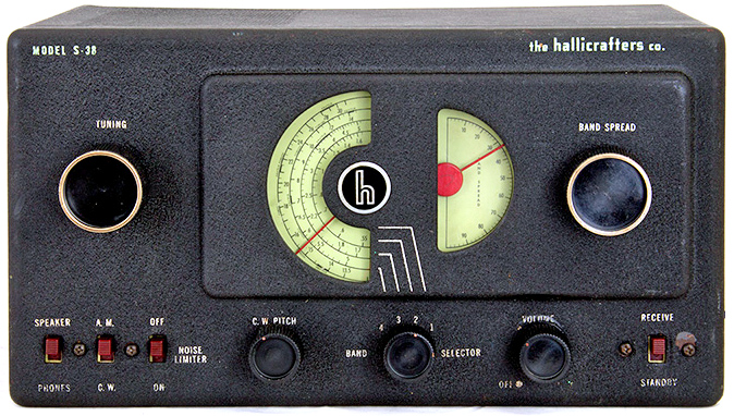
The S38 was their ubiquitous entry-level shortwave receiver intended for the general public. It was a simple transformerless All-American Five circuit that would receive the AM broadcast band from 540-1650 kHz and then continue through shortwave bands from 1.65 – 32.00 MHz over four switchable bands. The S38 was designed by French born American industrial designer Frank Loewy whose story is another fascinating rabbit hole I recommend those who are curious and appreciate 20th century design to venture down.
The venerable and ubiquitous original Halicrafters S38 – my gateway radio to the shortwave bands.
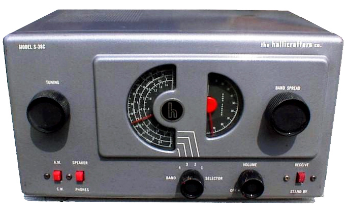
The S38 was surprisingly sensitive, inexpensive, simple to operate and remained in production until 1957 with regular design and minor circuit upgrades along the way. The original S38, produced until 1949, was the only radio in the series to feature a tunable BFO to allow the listener to easily peak CW and SSB signals. All following models lacked this feature and these included the S38A, launched in 1949, the S38B, launched in 1950, the S38C, launched in 1952, the S38D which came out in 1955, and finally the S38E which was introduced in 1957.
The S38, A, B and C all featured the distinctive two semi-circular tuning dials – a main dial on the left with a band spread dial to its right, giving these radios a distinctive trademark appearance. The D & E abandoned the circular dual dials for linear dial scales that occupied the majority of the front of the radio.
Model S-38C – similar to the model A & B before, lacking the CW PITCH control, the C featured a light on dark dial scale and a lighter grey cabinet.Model S 38-E – last of the line and featuring smaller tuning knobs and a linear dial scale.
Reliving that first magical night
I remember my surprise when dad came home from work that night with the S38. Dad’s nightly return to our apartment each evening just after 5 pm was always a moment of excitement for my sister Kristen and me.
For many of our childhood years we’d listen to hear his car pull up and then rush to greet him as he walked through the gate of our yard. Some nights were made even more wonderful when he’d be carrying a surprise gift for us kids.
Those were the best nights when dad had a fresh roll of Kodak 620 film for my hand-me-down Brownie Hawkeye, and of course the most wonderful night came a couple years prior when he brought home “Shadow” a black Cocker/Brittany spaniel mutt who became our beloved pet for the rest of our childhood. All of dad’s wonderful surprises thrilled us, but the night dad walked in with the S38 trumps all – yes, even the dog!
Dad said we could set the radio up after dinner, which seemed to go on forever that night. Worse, after dinner I had to wait further until the table was cleared and he finished washing and drying the dishes – his evening practice of expressing gratitude for mom’s fine cooking and a means to partner with her in mealtimes.
Finally when his evening chores were done, dad brought the radio to my bedroom with a spool of hookup wire, his wire nippers and a flat blade screwdriver. He set the radio up on my desk, using the tools to cut a 20′ wire antenna that he attached to the A1 terminal on the back of he radio. I crawled under the desk to plug in the power cord and we were ready to go.
From the 1946 S38 User manual
Dad pointed out the on/off/volume control and invited me to turn the radio on. I did and watched eagerly as the dial lamps came on brightly and then dimmed as the tubes began warming up. A few moments later and for the first time in my life, I heard was the beautiful strange syncopated sounds of Morse code coming from the built in speaker.
I of course had no ability to understand what I was hearing, but I was mesmerized by the sound of the rapidly sent dits and dahs. I pondered what urgent messages were being sent and I envisioned radio operators in their darkened shacks hunched over their Morse code keys before stacks of glowing radio equipment. A child’s imagination is a wonderful thing!
In my young mind’s eye…
After listening for a while, I tried turning the right hand bandspread dial slowly up and down, and continued picking up many other stations sending Morse Code. I was struck how these signals varied in terms of tone, strength and speed. I discovered that by turning the CW PITCH knob I could change the tone of the dits and dahs and peak their strength. Most of the code I was hearing was being sent rapidly, probably 20-25 words per minute or faster, but then there would be other stations sending slower code at 12 words per minute or less. It was all music to my ears.
Next I tried turned the main tuning dial up and down across the bands, without knowing the band plans or where I might find specific types of stations. Still by using my crude hunt and seek tuning method, the sounds of Morse Code were soon replaced by the distinctive distorted Donald Duck sound of hams operating phone on sideband.
I was captivated listening to the back and forth conversation between a pair of hams, exchanging a series of numbers (signal reports, power output, antenna specs), and some then ‘chewing the rag,’ \shooting the breeze and talking about whatever was on their mind – simple friendly conversation. I would marvel hearing the ham operators state where they were operating from – distant cities and towns across the US, being heard so clearly, and I was further thrilled hearing each operator routinely conclude his turn by giving his callsign. Wow – simply – wow!
Over the next few nights I continued to explore the shortwave bands and discovered more of what they had to offer. Hearing Morse code was magical, even though I couldn’t comprehend what was being communicated, and as wonderful as the hams on sideband were, most of their conversations began to sound the same.
This is when I first heard international shortwave broadcast stations such as the BBC, the Voice of America, Radio Moscow, and dozens and dozens of others from all over the world. Of course growing up in the 70s, I was coming of age in the height of the Cold War and all nations, whether from the East or the West, would have state sponsored shortwave station that broadcast the daily news and their editorial views nightly. It was a real education to hear how the same global news story could be reported so differently when presented by a Western station such as VOA, BBC or Deutsche Welle, or by an Eastern bloc station like Radio Havana, Radio Tirana or Radio Kiev.
Job 08-A2-294 Master Poster File 306-PPA-181
The international shortwave bands were chock full of Cold War propaganda!
After the news & views content that started every broadcast, the majority of these international broadcast stations would then move onto cultural and entertainment programming. Several had ‘mailbag’ programs where listener letters were read on the air and responded to. Some stations had language lesson programs, some reported on local cultural customs and seasonal events such as festivals, and most had ethnic music programs.
What a world that Frank’s simple gift of the S38 opened me up to. Recall that these were the days long before the internet, streaming video, and even basic cable. Up to then I was living in a world of three network TV stations plus the PBS station, and all that AM and FM radio had to offer.
More about the S38
As I mentioned, the S38 was ubiquitous in its day, and despite having concluted production 60 years ago, these radios remain ubiquitous in the radio hobbyist community today. It’s almost impossible to attend a ham radio flea market without seeing several, and there are dozens continually up for bids on eBay.
Similarly, there are many excellent web resources where S38 enthusiasts have published the receiver’s history, technical data such as schematics and servicing instructions covering essentials such as recapping and realignment, as well as performance and safety mods. I will conclude this blog entry below with a few links to some of my personal favorite S38 websites. But, while web certainly didn’t need another S38 fan page, given the radio’s foundational role in my radio story, I would be lacking had I never included a post such as this in my radio blog.
ORIGINAL PRINT ADVERTISEMENTS FOR THE ORIGINAL S38 (left) AND THE LAST EDITION S383 (right
S38 Specifications
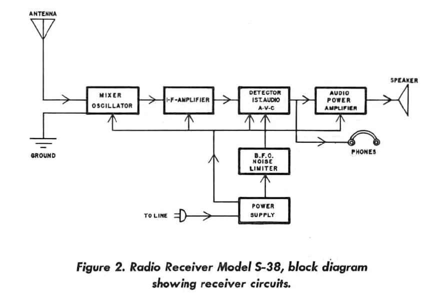
The S38 is a superheterodyne receiver using frequency mixing to convert a received signal to a fixed intermediate frequency (IF) which can be more conveniently processed than the original carrier frequency. Quoting the S38 1949 user manual…
Radio signals are picked up at the antenna and fed to the antenna coil of the mixer stage where the desired station signal is selected by a resonant circuit and fed to the mixer tube. At the same time, the oscillator section of the tube generates a local r-f signal which is mixed with the incoming station signal. An intermediate frequency of 455 kc is selected by the first i-f transformer and fed to the i-f amplifier tube where it is fed throught the second i-f transformer to the dectector-first audio amplifier where it is demodulated. The audio component of the signal is then amplified by the triode section of the tube and capacity coupled to the audio output tube where it is further amplified and fed to the speaker.
The Hallicrafters Co., Installation and operating instructions for the model S-38 radio receiver, August, 1946, 94-162-A
The S38 circuit was the popular “All American Five” design, which was used in hundreds of radio sets by practically every radio manufacturer of the era. The AA5 was a sensitive superheterodyne circuit that lacked a power transformer and could be operated using either an AC or a DC power supply of 115-125 volts. By not including a power transformer, AA5 radios provided an inexpensive radio choice for the consumer of the day.
However this cost saving feature also contributed to making these radios a bit more dangerous for the user. Typical of radios and electric appliances of the 1940s, the S38 did not have a polarized plug on its line cord which means you have a 50% chance of connecting the chassis ground side of the radio to the household ‘hot’ connection rather than the safer neutral connection. This had the potential of resulting in a dangerous electric shock for the user if the rubber washers that insulate the chassis from the cabinet deteriorated and failed. Because of how the on-off switch was wired in this ‘hot chassis’ design, the risk existed even if the radio was switched off.
An essential practice for anyone servicing or restoring an S38 today is to install a polarized plug and wire it so the neutral wire goes to ground and the hot lead is connected to the power switch which is relocated to pin 2 of the 35Z5 tube on the opposite end of the filament chain. Adding a fuse to both power leads is also a good idea. Whenever I restore an S38, in addition to replacing the leaky wax and electrolytic capacitors, I make the following modification.
S38 Links
Phil Nelson has maintained his excellent website dedicated to restoring the Halicrafters S38 since 1995 and its an excellent starting place if you want to learn more about the S38. He also has instructions on how to add an S-meter to your radio.
WD4EUI, Allen Wooten of Huntsville, Alabama has an excellent page on his restoration of an S38C complete with excellent detailed photos including several on repairing damaged IF transformers.
The Sam’s Photofact for the original S38 model, including schematics, parts list and alignment instructions can be obtained as a PDF here.
John Fuhring describes his restoration of his S38B complete with detailed photos and a schematic for a mod to add an FET based BFO here.
Read reviews of the S38 from ham radio operators on the eHam product review site here.
AI4FR, John Whitt of Dade City, Florida has a detailed page dedicated to his resto-mod of an S38 including his safety modification to prevent shocks.
VE7SL, Steve McDonald of British Columbia describes his S38 restoration here.
As I said, there are no shortages of websites dedicated to S38 restoration and use. Thanks for visiting mine and reading my personal story.
Do you or did you own an S38? Which model was it? Did you restore it or modify the radio? Do you still use it today? What are your thoughts or impressions? Drop me a line a james@ab1dq.com and share your story!
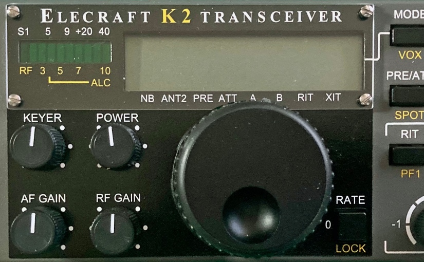
This morning I completed the Front Panel Board, the second board of the Elecraft K2 HF Transceiver Kit build that I began at the start of the year. After completing the Control Board on January 17, I took a complete month off working on other weekend projects before starting the Front Panel on February 21. I did state from the get go that I was going to take my time with this, my most ambitious kit build, and I’m staying true to my word.
The Front Panel Board is where all of the user controls are mounted. These include the large rotary encoder/tuning knob, the numeric keypad and pushbuttons, and five variable resistors. This section also includes the graphical LED status bar display and the LCD main display.
Assembly of the front panel starts by soldering the sixteen tactile push button switches to the printed circuit board. For a proper and neat professional appearance, it’s essential that all of the switches be mounted at a precise uniform distance from the surface of the board.
Elecraft provides a nifty switch spacing tool in the kit which is essentially a thin narrow bit of PCB material that is placed under each switch which is then pushed flush to the spacing tool. This clever method worked exceptionally well for me.
After the switches are mounted, the board is populated with the usual components – resistors, capacitors, diodes and transistors. The front panel board has four ICs including the large 40 pin U1 which is mounted on the bottom side of the board and behind the display.
The front panel board also has a good bit of hardware to be attached including the eight-pin microphone jack and several spacers. Up to this point the instruction manual has been absolutely excellent in providing detailed easy to follow accurate directions.
However, I did encounter some difficulty when it came to mounting the main display components which consists of two backlight LEDs, their spacers, a white cardboard reflector, a frosted plastic diffuser, and the 40 pin LCD.
As I discussed in my previous post, the Elecraft K2 is a fabulous kit, but it’s a rather old kit, first prototyped a quarter century ago – in 1997! Understandably in the time since its introduction, some components become ‘unobtainium’ as the years go by. Vendors come and go and with advancing technology, manufacturers discontinue production of now archaic through-hole components with today’s increasing popularity of SMD architecture.
Thus, when one buys a K2 kit today, it will come with several pages of errata that must be carefully consulted and reviewed. Builders in 2022 will find themselves crossing out sections, sometimes whole pages, of the original manual, and adding notes about the replacement modern components packaged with their kit.
This was the case with the display assembly. I was instructed to cross out most of the directions pertaining to the installation of the display on pages 27 and 28 of the manual and to follow the alternative directions provided as errata.
The revised directions call for the builder to first insert the leads of a pair of rectangular LEDs through plastic spacers and solder the LEDs flush to the board to the left and the right side of where the LCD will be mounted.
Between the two LEDs, the builder places a white cardboard backlight reflector and then mounts a frosted plastic diffuser by placing it over the the two LEDs on the left and the right side. The diffuser has an indent on each side to accomondate the LEDs.
I found this all went precisely as described until I came to the step that instructed me to place the LCD flush on top of the diffuser and then solder the 20 pins of the LCD to the associated pads on the PCB.
None of the LCD pins were long enough to go through the holes in the pads on the board. If pressed flush to the diffuser the LCD pins just barely touched the pads.
With the LCD flush against the frosted crystal diffuser, the pins are too short to penetrate the holes in the pads.
A view of the bottom side of the board showing the inadequate length of the LCD pins.
I carefully checked the instructions and my work. I was certain I mounted the LEDs correctly and flush to the board with their spacers, and the cut outs on the bottom side of the plastic diffuser neatly accommodated the LEDs perfectly.
Realizing that proper positioning of the LCD would be critical for the PCB to properly fit in the front panel and knowing that not getting the spacing correct would also give the finished radio a sloppy appearance, I reached out to Elecraft for help via their website.
I dreaded the prospect of having to de-solder 20 pins and run the risk of damaging the LCD if I needed to remove it after it was soldered in place. I wanted to get as much information as I could before proceeding.
I received an email reply from Dave at Elecraft who is their K2 support guy within a couple of days. Dave stated that it was ‘perfectly normal’ for the LCD pins to just touch the top pads on the PCB and that they do not need to protrude through the holes. He said that his last K2 build was like this and suggested that I carefully solder the 20 pins from the topside, but to make sure the LCD is level and parallel to the board.
I did as Dave recommended, carefully aligning the LCD so it was level and evenly spaced above the board. I started by soldering each of the corner pins and confirming the LCDs position after each solder joint. Once done, I applied solder to the pads on the bottom of the board to let it flow through the hole to help ensure solid contact.
However, after I soldered just under half of the LCD pins, I realized I had left out the cardboard reflector. D’oh! There was no way I could slide the stiff cardboard under the pins at this point and I didn’t want to have to de-solder so many pins, so I came up with a workaround.
I took a piece of white copier paper and cut a rectangle to the same size as the cardboard reflector. Cutting the paper in half, I was able to slip both halves between the gap in the pins on the bottom of the LCD and position them in proper place. I held them in place with a bit of cellophane tape.
From here on out the rest of the front panel assembly went smoothly. Again I encountered the need to reference the errata for the main encoder knob as Elecraft includes a different unit than the one referenced in the original instruction manual. The encoder in my kit required me to solder a few parts into an auxiliary board to which the encoder was attached. The auxiliary board is then attached to the back of the front panel board.
The rotary encoder auxiliary board.
The last step was to mount the completed front panel board inside of the front panel. Before doing so, the manual lists about 30 resistance checks for the board. Each test point checked out as specified to ground – excellent!
I was very pleased that after I carefully mounted the board the front panel looked perfect. All of the push buttons were a proper and uniform height through the holes on the panel. All knobs, including the main encoder dial, were also correctly mounted and turned with ease. Best of all the main display LCD that caused me so much grief, looked perfect under the front bezel.
Completed Front Panel PCB, front.Completed Front Panel PCB, back.The completed front panel…. it ‘looks’ like a radio anyway.
“Unique ham radio kits for the budget minded.” That’s what the masthead proclaims on the QRPGuys website and that is exactly what you’ll find there – a collection of project kits for the builder/QRPer that aren’t found on other kit sites and all offered at a more than fair price.
Current transceiver kits include their AFP-FSK Digital Transceiver, now in its third edition and they also offer a wide variety of other QRP essentials including several antennas and tuners, test gear including power meters, attenuators and filters and other accessories,
The QRP Guys are an affiliation of a “who’s who” of QRP building and will give you an idea of the innovative and high-quality products they develop. Ken LoCasale (WA4MNT) provides kit mechanical design, board layout and documentation, and NorCal cofounder Doug Hendricks (KI6DS) is credited with logistic support and beta testing.
Circuit design is by Steve Weber (KD1JV) of Pacific Antenna, Dan Tayloe, creator of the N7VE SWR Bridge, and Cliff Donley (K8TND). Both Steve and “Kazu” Terasaki (AG5NS) author firmware, technical assistance is given by beta builder Yin Shih (N9YS) and John Stevens (K5JS) is credited with assisting Ken with website maintenance.
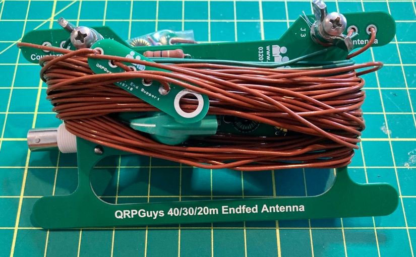
Building the QRPGuys 40-30-20 M End Fed Antenna
The QRPGuys multiband end fed antenna meets my definition of an easy build with only 16 solder-in components on the main tuner circuit board and the two traps. I started as I do with all of my kit builds by inventorying and arranging all of the parts. I have been using cigar boxes with clasps on their lids to prevent me from losing small parts before they are needed. Cigar boxes are also ideal for storing works in progress kits when a project will extend beyond a single building session.
This easy to build kit has a minimal number of parts.
The prospective builder should be forewarned that of those sixteen components, four of them are inductors that must be hand-wound on toroid coil forms. Many builders seem to abhor the winding of coils, and while I find it sometimes fiddly work, I’ve come to not mid the process.
I give props to the writers of the QRPGuys manual, as they provided some of the clearest instruction on how to wind the inductors, including the number of loops and where to place the taps. The manual also includes a nicely done illustration of each inductor and hints on how to assure the builder wound them correctly.
The diagram from the instruction manual clearly depicts how to wind the four inductors.
The inclusion of Thermaleze® brand magnet wire for the inductors was also a nice feature – the enamel coating was quickly dispatched after a few seconds of exposure to my Zippo cigar torch.
The entire build, including the winding of the four toroids, building the traps and measuring the three driven element lengths of wire took me less than 2 hours working at a leisurely pace on a winter’s Sunday morning.
BeforeAfter
About the Antenna
Field testing this antenna will have to wait a few more weeks for more reasonable weather here in Connecticut, but my plan is to use this antenna for QRP POTA activations this year with various homebuilt radios such as the Ramsey QRP20 transmitter I assembled last week. The end-fed design should make for easy deployment as a sloper while operating from the field with easy access to the tuning controls from my operating position.
The tuner circuit design is as straightforward as it gets – your basic tunable L-C circuit with a varicon capacitor. But the kit also employs the N7VE LED absorption bridge that keeps SWR to a minimum of 2:1 when set to the tune position. According to the kit documentation, the LED indicates only reflected power. Full LED brilliance will indicate an SWR at 4:1 or greater. At half brilliance SWR is approximately 2:1, and the LED will completely extinguish at 1:1.
I was impressed with the apparent high quality of the PCBs and components, and I found the instructions and supporting documentation to be exceptionally well written – easy to follow and understand.
If you would like to build the QRPGuys Multi-band End Fed Antenna, you can purchase the kit on their website here. The current price of the kit is $40 USD.
If you have built this kit, or have any questions or comments, please feel free to leave a comment or drop me a line at james@ab1dq.com.
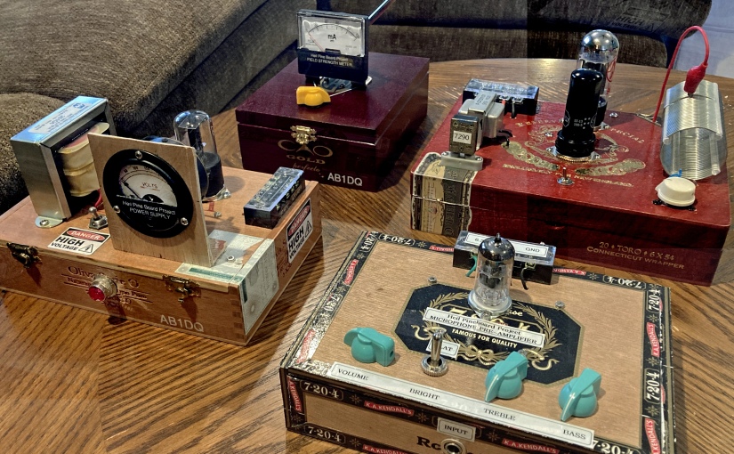
The second build in Bob Heil’s Pine Board Project is the power supply. Both the transmitter as well as the pre-amplifier feature vacuum tubes which means they require a high DC voltage for the tube plates (B voltage) as well as a lower 6.3 VAC filament voltage.
I had previously built the AES K101 battery eliminator kit for my vintage Arborphone coffin radio, which I no longer needed it for. The K101 is currently collecting dust on a workshop shelf and would have worked well with the Pine Board project. But building is fun, and Bob provided schematics and instructions for a nice simple classic tube power supply designed around the 6X5 rectifier tube.
Thanks to Bob’s excellent online documentation and HamNation videos, I had no difficulty building the power supply. The only modification I made to my build, besides choosing to mount it in a cigar box rather than on a slab of pine, was that I added a neat-O vintage NOS voltage meter.
My first build of the Heil Pine Board Power Supply w. voltage meter (left). Wiring neatly hidden away on the bottom side of the cigar box lid (right.
The power supply worked great, put out about 180VDC B+, and it looked great (to me anyway!)
However, a couple of months ago, when I finally completed my build of the transmitter (watch for my future blog post), I was disappointed to record less than one watt into my dummy load on both 40 and 80 meters. I assumed I had botched something in my transmitter build and began to retrace and double check my work only to discover that all looked right.
I went back to Bob Heil’s Pine Board Project website and discovered that since he published the original plans for the power supply, which I had used, he had since uploaded modified plans replacing the 6X5 rectifier tube with a solid-state bridge rectifier. In a more recent video upload, Bob explained that changing the rectifier would result in a significant increase in B+ voltage and that it would in turn increase the transmitter RF out to the neighborhood of 5 watts.
Following the updated schematic and layout plan, I modified my power supply but soldering a bridge rectifier to an octal tube base and disconnecting the center tap on the power transformer as instructed. This worked as described – my B+ voltage was now approaching 400 volts and the transmitter was putting out over 4 watts into my dummy load.
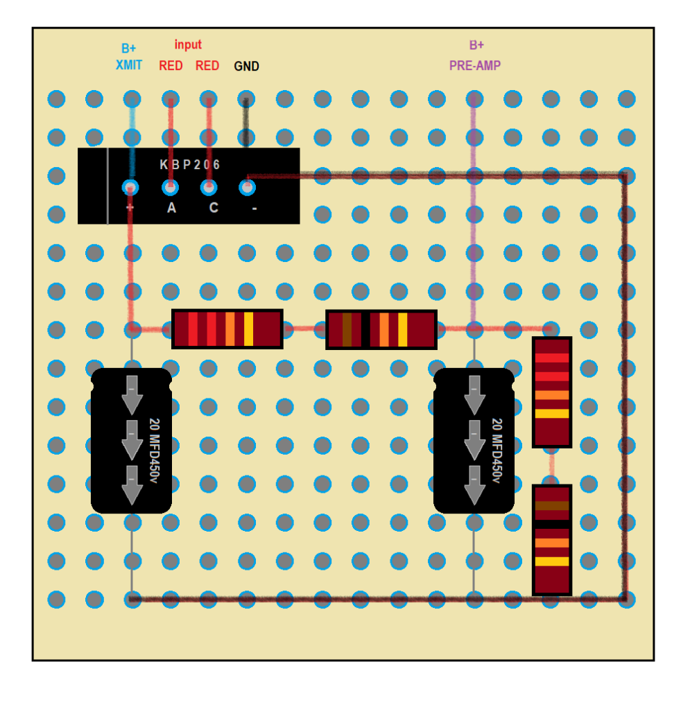
However, all was not right in the world. Upon closer inspection of the revised schematic, I saw that where there was a single B+ output originally, the capacitor/resistor network was reconfigured with two taps so a B+ of lesser than 200 VDC would be available for the 12AX7 tube in the pre-amp. According to the datasheet, the plate voltage on the 12AX7 should not exceed 300 volts.
I attempted to modify my power-supply for the second tap but ran into difficulty doing so. The version I build had included a third filter cap but the Heil redesign returned to two filter caps. I became vexed and now realized I had misunderstood the bleed resistor in my initial 3 cap build to be part of the resistor voltage drop circuit in the newly published solid-state design. Regardless of where I tried to tap the circuit for the second B+ voltage, it always equaled the near 400+ volts I was now getting on my first tap.
I decided since I had a bag full of bridge rectifiers, a drawer full of 20 MFD 450V caps in my workshop, I would salvage the transformer and begin a completely new build of the power supply this weekend working directly from the new Heil schematic.
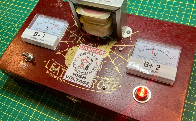
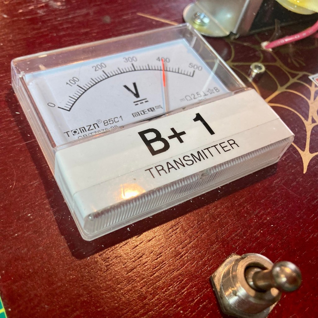
I wanted to expand on my meter mod – since the power supply would be providing two different B+ voltages, I planned to add a second meter so I could easily confirm that B+1 for the transmitter and B+2 for the pre-amp were not the same and appropriate for their respective circuits. I purchased a pair of modern 500 volt meters since my vintage NOS meter I originally used maxed out at 300 volts.
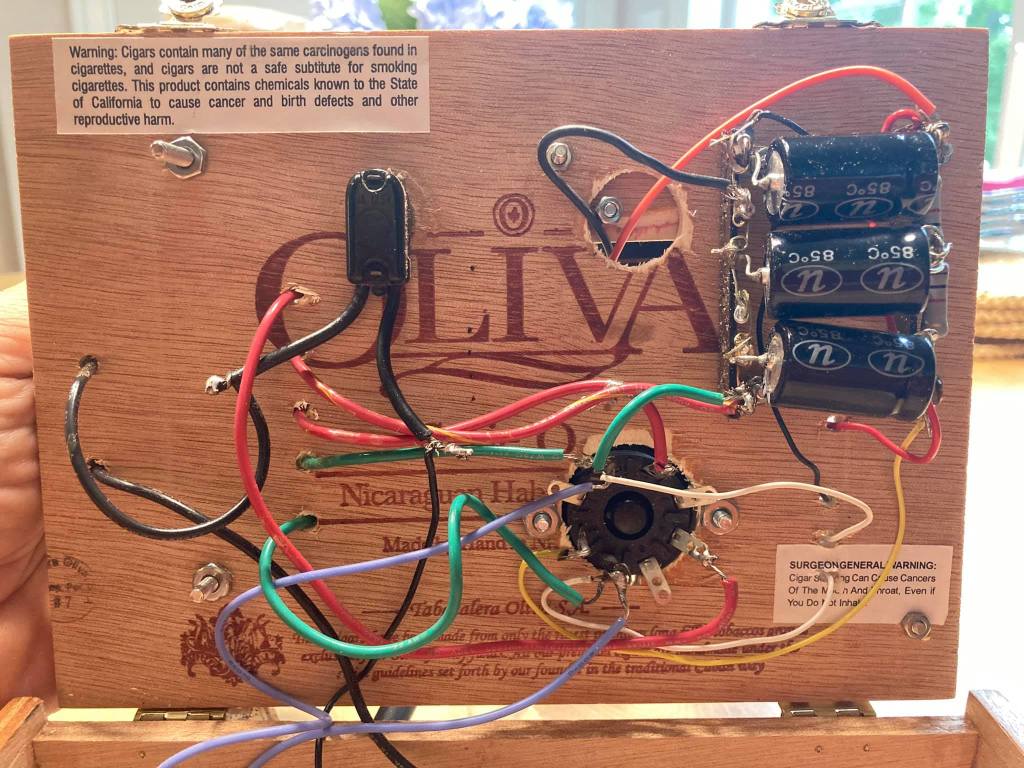
I also decided since all of the components excepting the power transformer and meters would be mounted on the bottom side of the lid, I would abandon the terminal-strips and point-to-point wiring and instead use a perforated PCB board to make a subassembly for the filter caps and voltage drop resistors. Working rom the schematic, I designed the layout on my PC first and the built to my design.
PCB layout design left, actual on right. I did not have any 33K ohm 2-watt resistors on hand, so I wired 2 22Ks in series with a 10K each to get ‘close enuff.’
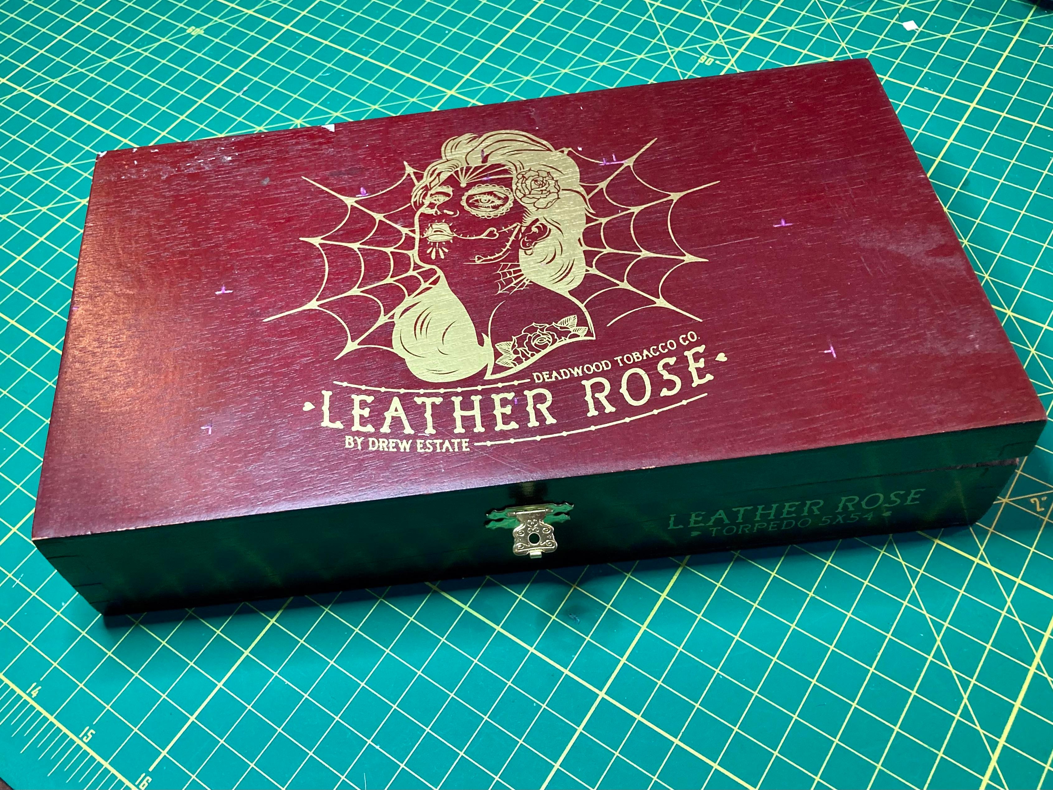
Next, I chose an appropriate cigar box from my stash for the build. Since I planned to mount the two meters to the top of the lid this time, I chose my Leather Rose cigar box as it was the widest. It was an excellent choice, I think, with one problem.
The shallow wide box was designed to hold a couple dozen cigars and the lid only needed to seal the box to protect the contents from drying out. The strain put upon the flimsy staple hinges by the heavy transformer was a bit much and I plan to replace the hinges with sturdier ‘real hinges.’
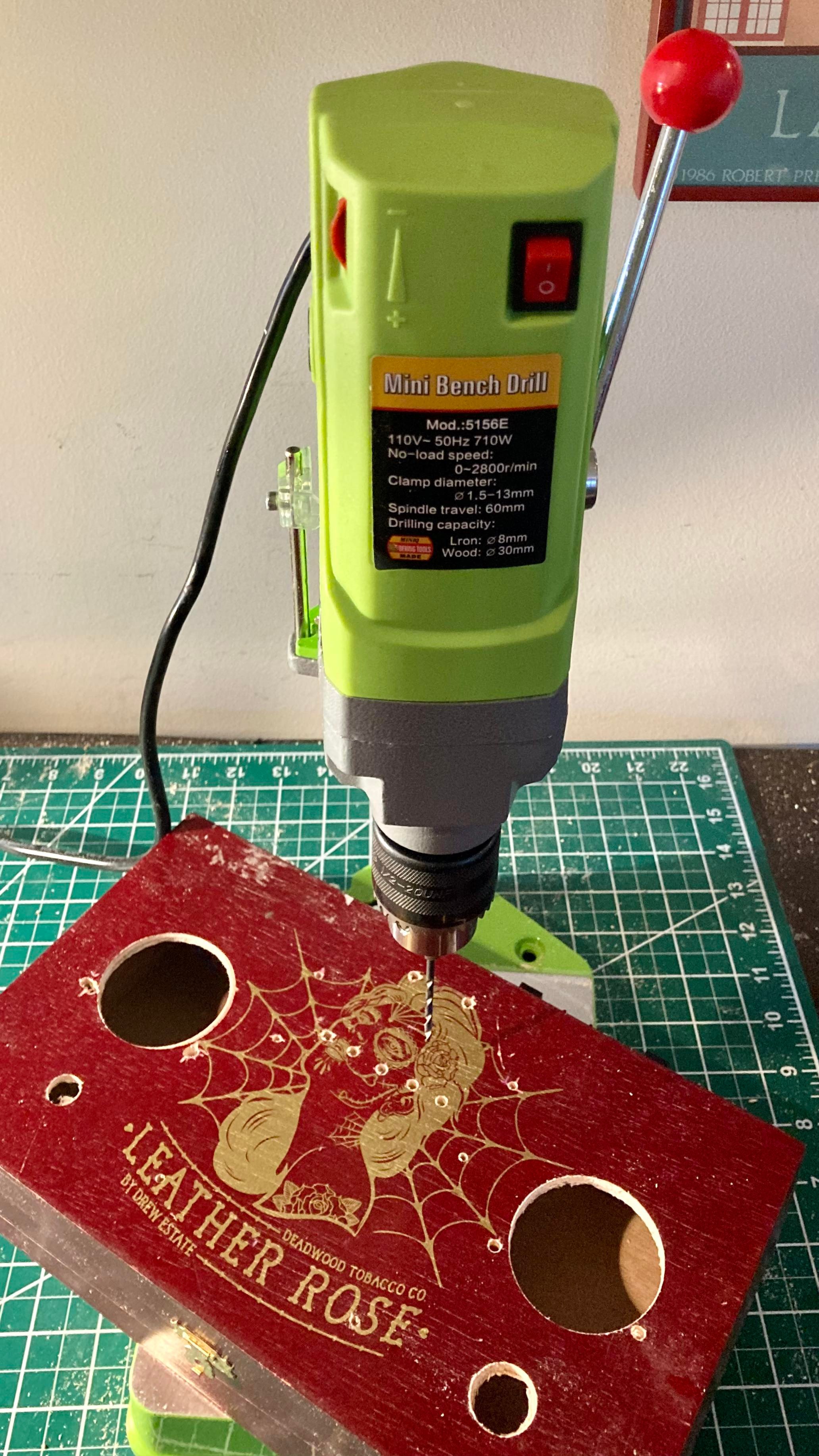
I loved the artwork on the Leather Rose cigar box (left), it was a shame to drill into it, but drill I did. Using the new mini drill press my sister Kristen had just gifted me for Xmas, I did some precision chassis drilling in short order (right).
Once the chassis was drilled out, the rest of the assembly went smoothly and quickly. Having all of the capacitors and resistors on the PCB subassembly made for short work of all connections once the board and other chassis mounted parts were attached. Before mounting the transformer, I made all of the output connections and built a ground bus. Once the transformer was attached, it did not take long to wire up the power cord, fuse, switch and 6.3 VAC pilot light.
A look under the hood, shunning point-to-point connections for the PCB subassembly saved time, space and made for a neat construction.
I completed all of the work over my Saturday and Sunday morning this weekend, working slowly and carefully. My patient deliberate methods paid off as there were no snap, crackles or booms or smoke or open flames when first fired up.
Look Ma – no smoke!Left: B+ No. 1 will be delivering nearly 400 VDC to the transmitter. Right: B+ No. 2 will provide the 12AX7 tube’s plate with a safe 190 VDC.
Finally, I want to acknowledge that this project produces lethal voltages, something we don’t deal with much anymore in this era of silicon devices. I grew up mucking around in high-voltage hollow state radio & TV chassis, and I am well aware of the proper precautions necessary for safety’s sake.
Despite the fact my regular practice is to discharge electrolytic caps and I try to be super mindful about knowing what I am touching with my hands when exploring a circuit, still I managed to shock myself a couple weeks ago while trying to diagnose why my two B+ voltages were the same after I did the first solid state mod. I was holding the power supply in my hand with the box opened, visually examining the circuitry when I accidentally touched the power out terminal strip on the top side of the box lid with my right hand.
Fortunately, despite my negligence, I did have my left hand in my pocket, a good safety practice I learned early on to prevent lethal currents from passing through the heart. That said, I encourage anyone who may be inspired by my blog and Bob Heil’s excellent plans to give this project a try – do be knowledgeable about the dangers of working with lethal voltages and how to be safe. In the end, you are solely responsible for any risks you take building or working on such circuits.
Reddy Kilowatt may seem to be a funny guy, but he does mean business!
Have a comment, question, or a personal experience to share? Post a reply or please drop me a line at james@ab1dq.com.
Legendary sound engineer Bob Heil, architect behind many signature rock artist signature sounds (The Who, The Grateful Dead, Peter Frampton, Joe Walsh to name a few), is also renowned in the amateur radio community.
Bob has engineered and his firm Heil Sound retails high performance microphones and other premium gear for the ham community, he has authored books and numerous articles for the ham community and is one of the most sought-after speakers for amateur radio conferences. Bob hosted the popular TWiT video podcast HamNation from 2011 through 2020; archived copies of the podcast remain a valuable resource to hams today.
In the Spring of 2017, Bob Heil introduced to the amateur radio community, The Pine Board Project, afour-part do-it-yourself AM transmitter project. In earlier times, building your own gear was a larger part of the ham radio experience. RF theory and design made up a larger portion the exam material and while studying, many prospective Novices would construct their own basic receivers and transmitters while studying for their licenses.
Plans for these projects were widely published – from the American Radio Relay League’s handbook and monthly magazine, QST, to other popular radio and electronics magazines such as CQ, 73, Popular Electronics, Radio TV Experimenter, and Elementary Electronics.
The Heil Pine Board project was a throw-back to these times. Bob broke the project into four separate sub-projects for the builder to construct: an RF field strength meter, a high voltage power supply, an audio pre-amplifier and equalizer, and a 40/80-meter transmitter capable of approximately 5 watts AM output.
Several episodes of HamNation included featured segments in which Bob would take the prospective builder through circuit design, parts layout, and circuit theory. Bob published the schematics and board layout diagrams on the Heil website and even provided parts lists with sourcing information, giving the names of firms that carried some of the obscure parts from an earlier era, along with stock numbers and prices.
Bob’s enthusiasm for the projects as expressed in the videos was infectious. His presentation style was straight forward, detailed and inviting for the new builder. Along the way he featured photos and reports of viewers’ work.
I was hooked from the get-go. I grew up spending hours on ends in my grandfather’s TV/radio workshop in our basement and had read dozens and dozens of articles for building projects that appeared in the yellowing pages of his electronics magazines from the 60s. I had built many an electronic kit in my time, but beyond the occasional simple crystal radios or basic transistor circuits, I never did much scratch building.
I started building the projects a couple of years ago, closely following the directions and completed the field strength meter, the power supply and the pre-amplifier. Then, true to form, I either got distracted by other things (other projects, family, work, life itself).
Last summer (2021) I made a resolution to focus and complete the unfinished projects on the shelves of my workshop and decided it was time to complete the Heil project.
Friends who know me well, know that in recent years I had enjoyed the occasional cigar. Many a workweek transitioned into the weekend by enjoying a fine Leaf by Oscar and an Old-Fashioned with my dear friends Carl & Steve at the Owl. Every week or so, the Owl staff would leave empty wooden cigar boxes out at the curb for folks to take and I started nabbing a few thinking they might make good chassis for ham radio projects.
Since then I had built a few recent projects into my cigar boxes and thought that it might be fun to put my cigar box spin on Bob Heil’s transmitter project and built the transmitter into a cigar box and then rebuilt the other projects into their own cigar boxes.
At this point I’m going to blog on my Heil Pine Box/Cigar Box Project experience in a series of articles, starting with the power supply. As I mentioned I initially built this on a pine board and my initial build used the 5XT rectifier tube using Bob’s original design. I have replaced the 5XT with the solid-state rectifier, building the modified power supply as designed by and published by Bob.
Thanks again to Bob Heil for designing and sharing and promoting the Pine Board Project – it has provided me with hours and hours of enjoyment so far, and there’s much more fun ahead.
Have you built the Pine Board Project? Leave me a comment or drop me a line at james@ab1dq.com. Jump to my post about my power supply build here.
As the proverb goes, a journey of a thousand miles begins with a single step. So, after procrastinating for two plus years after my XYL and soulmate Ellen gifted me the Elecraft K2 HF Transceiver Kit for our tenth anniversary, I finally got my nerve up to start what will easily be my most ambitious kit build ever.
It is my intent to blog about my experience as I proceed, circuit board by circuit board, sharing my experience and inviting others who have built the K2 to share as well.
The Control Board
Having set up and outfitted a new protected work bench using a folding banquet table in the shack where I will work only on the K2, I started work on the first circuit board, the Control Board on January 9, 2022.
As with many kits I’ve built, the Elecraft instructions call for the builder to start by inserting and soldering all of the fixed resistors first. As others have reported, I found the instructions to be, for the most part, very well written. The instructions for the fixed resistors provided each resistor’s value in ohms as well as the color code and the builder is encouraged to install the resistors with the first color band towards the top or the right of the circuit board to facilitate verifying the correct resistor is in the correct space when reviewing or troubleshooting your work.
As electronic components have gotten increasingly smaller, my vision has gotten progressively worse as I’ve gotten older. Whenever kit building, I always verify values with my VOM before inserting any resistors into a circuit board. After installing the 13 resistors, the instructions called for the installation of seven resistor arrays and one trimmer pot, all easily identified.
The Control Board after installing all resistors.
Next the builder needs to install an 82 mH inductor, which I confirmed I had the correct part with my L/C meter, followed by a pair of silicon diodes. I then encountered the first variation in my kit. Where the original PCB had a screened space for D3, the instructions called for an 82K ohm resistor to be installed here.
The instructions next call for the builder to install and solder in place 36 fixed capacitors. Identifying and verifying the value of each capacitor was a notable challenge. Not only were the stamped or printed values on the caps miniscule, the capacitors also varied in type, shape, and manufacturer and it was clear that some of Elecraft’s suppliers changed over the twenty-five years they have been offering the K2 kit, as some of the caps did not match in appearance to the identifier pictures in the otherwise excellent parts list in the appendix.
To guarantee I placed the correct capacitor in the correct space, I took the time to identify every capacitor and laid them out neatly on my workbench in the same order the instructions called for their installation.
To identify the values, I used the camera on my iPhone and zoom in on the part. Sometimes when the value is etched on the capacitor, I needed to shift it so my bench light catches the labeling just right to read. I took the time and used my L/C meter to verify the value of every capacitor.
LEFT: using my iPhone as a digital magnifier to read capacitor labels CENTER: checking capacitor values with an L/C meter RIGHT: laying out verified capacitors in the order of installation
Once all of the capacitors were laid out in the order of installation, I carefully installed each capacitor into its space, having taken the time again to double-check values with the L/C meter. It was a slow process, but in the end, I felt very confident all of the capacitors were soldered in the correct space giving me peace of mind. Trouble shooting for mis-placed capacitors would be a very tedious process if necessary.
The next several steps went along easily as I installed the electrolytic capacitors, a trimmer cap, a dozen bipolar junction transistors, a pair of crystals, two voltage regulators, one IC socket and various connectors. All of these parts were easily identified, and when working with the transistors, I proceeded in the same manner as I did with the fixed caps, identifying and verifying value, arranging them in the order of installation and double-checking values as I installed each.
The bipolar transistors, values checked and laid out in order of installation.
Now it was time to install the ICs on the control board, and this is where I first ran into trouble.
The very first chip was an NE602, the AGC mixer. I mentioned that the K2 has been on the market for twenty-four years and over the course of a quarter century, technology moves on and the availability of parts change. By the time Elecraft had kitted my specific K2, the NE602 was no longer widely available in through-the-hole DIP casing. The industry had since begun moving on away from through-the-hole components in favor of tiny, less expensive surface-mount versions.
Instead of the DIP version of the NE602, my kit came with an equivalent SMD NE612 which was pre-soldered to a small square ‘carrier board.’ The carrier board is a PC board cut to the same footprint of an 8 pin DIP case and the builder is instructed to cut eight 1-inch pieces of wire, insert them into the eight holes on the carrier board, solder them in place, then insert the bottom ends of these wires through the DIP-spaced holes and solder to the control board.
I damaged the carrier board while attaching the wires by working sloppily with a too-hot iron. The carrier board was not of the same high quality as the control board which featured double plated holes. The carrier board had plating only on the top of the holes, and I managed to lift the plating off of the number 2 and number 3 hole, breaking connectivity. I tried to bridge the contacts to the chip contacts with a solder blob, but that only made a bigger mess of things.
LEFT: the Control Board space for U1, an NE602 DIP RIGHT: The SMD carrier board for U1 which I damaged with a heavy hand and hot iron
Elecraft has a form on their website to order replacement parts and I reached out on January 1qth to inquire about purchasing a replacement NE612 and carrier board. I did receive an acknowledgement that they received my inquiry from a mail bot, but as of this writing, four days later I have not received an actual reply.
In the meantime, I began wondering whether I could still find DIP cased versions of the NE602 elsewhere online. I searched Mouser, Digi-key, eBay and Amazon and found that an Amazon vendor had some available, which I ordered. The vendor did not disclose the name of the manufacturer nor the source country, but I’m assuming the chips were manufactured in China. I did order five (there are three others elsewhere in the K2) and they arrived within a day or two.
I discussed my dilemma with one of my Elmers, Steve, KZ1S, who has built many a kit in his day and is a physics professor who works with electronic circuits and RF in his work.
Steve offered a couple of suggestions. The first was to use a proper SMD to DIP converter board with proper pins spaced correctly. I liked this idea very much, but the drawback is that it would require me soldering the SMD chip to the converter board and again, with my failing vision and dexterity, this would be a bit of an unpleasant challenge.
A proper SMD – DIP converter
Steve also suggested looking for genuine NOS chips online, either on eBay, or from Radwell International. Steve mentioned you can source just about any obsolete part with Radwell, but they can be expensive. I did locate the NE602s on there with a retail price of about $5 – not a deal-breaker, but given I need four for the K2, that’s an additional $20 + shipping.
For the time being, I decided to place a DIP socket on the control board and once in place, I inserted the NE602 of dubious origin I purchased from Amazon in the socket. For the time being this would let me continue with the build and be able to test resistances. I could then swap out the AGC chip for a genuine NOS or SMD + converter at a later date.
I finished the build of the control board this morning, directly soldering in the remaining ICs and adding the two CW key-shaping capacitors on the solder side of the board.
After carefully double-checking all of my work, I used my VOM to perform the resistance checks. All of my test resistances were within range, excepting U6 pin 29 (DASH) and U6 pin 30 (DOT/PTT) which were marginally over spec. The acceptable range for both is 70K – 90K ohms and I measured 96.6K on pin 29 and 96.8K on pin 30. I will revisit these values later.
So that concludes the build of the first circuit board, the Control Board. I counted a total of 110 components soldered to the board and I completed the work in eight days working at my deliberately leisurely pace.
I welcome comments and suggestions from any and all, particularly from anyone who has built the K2 and had to deal with the SMD carrier board themselves. Drop me a line at james@ab1dq.com to share your thoughts and opinions.