Control Board Assembly
As the proverb goes, a journey of a thousand miles begins with a single step. So, after procrastinating for two plus years after my XYL and soulmate Ellen gifted me the Elecraft K2 HF Transceiver Kit for our tenth anniversary, I finally got my nerve up to start what will easily be my most ambitious kit build ever.
It is my intent to blog about my experience as I proceed, circuit board by circuit board, sharing my experience and inviting others who have built the K2 to share as well.
The Control Board
Having set up and outfitted a new protected work bench using a folding banquet table in the shack where I will work only on the K2, I started work on the first circuit board, the Control Board on January 9, 2022.
As with many kits I’ve built, the Elecraft instructions call for the builder to start by inserting and soldering all of the fixed resistors first. As others have reported, I found the instructions to be, for the most part, very well written. The instructions for the fixed resistors provided each resistor’s value in ohms as well as the color code and the builder is encouraged to install the resistors with the first color band towards the top or the right of the circuit board to facilitate verifying the correct resistor is in the correct space when reviewing or troubleshooting your work.
As electronic components have gotten increasingly smaller, my vision has gotten progressively worse as I’ve gotten older. Whenever kit building, I always verify values with my VOM before inserting any resistors into a circuit board. After installing the 13 resistors, the instructions called for the installation of seven resistor arrays and one trimmer pot, all easily identified.

Next the builder needs to install an 82 mH inductor, which I confirmed I had the correct part with my L/C meter, followed by a pair of silicon diodes. I then encountered the first variation in my kit. Where the original PCB had a screened space for D3, the instructions called for an 82K ohm resistor to be installed here.
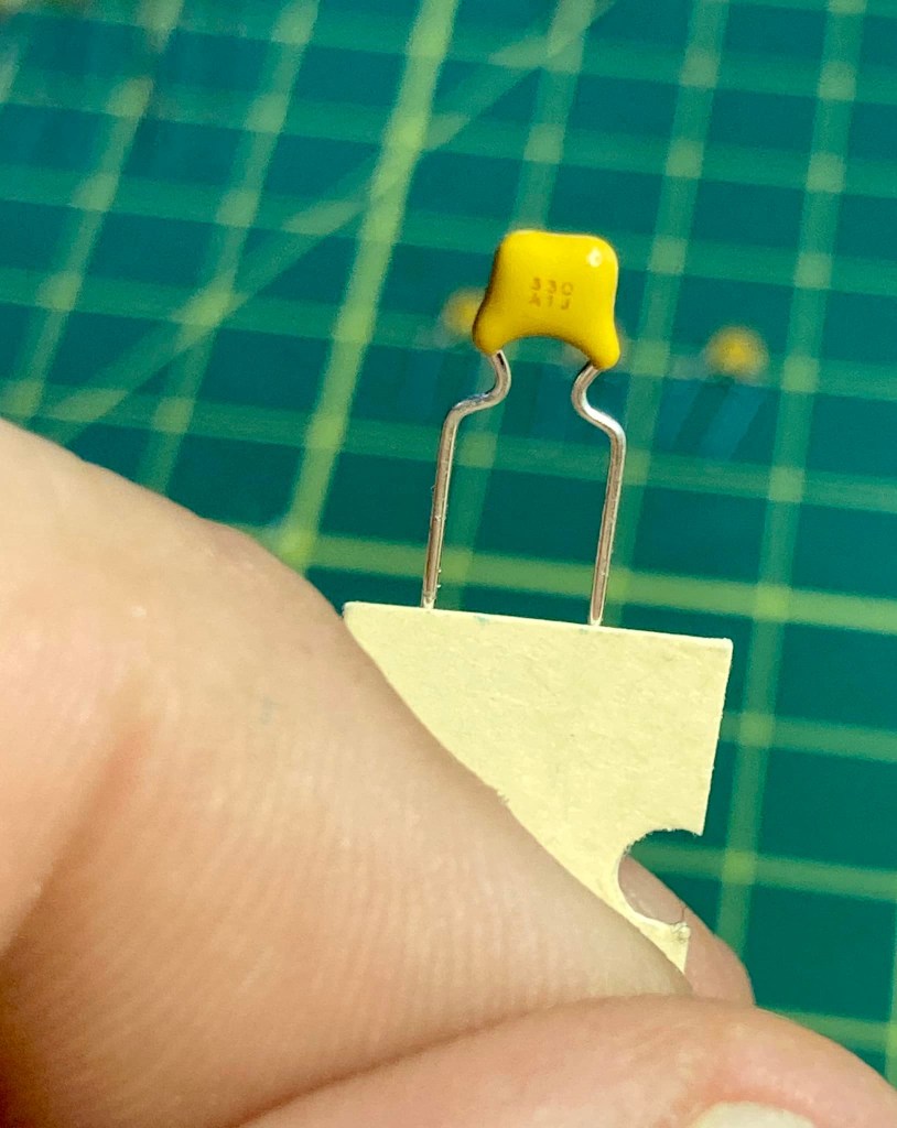
The instructions next call for the builder to install and solder in place 36 fixed capacitors. Identifying and verifying the value of each capacitor was a notable challenge. Not only were the stamped or printed values on the caps miniscule, the capacitors also varied in type, shape, and manufacturer and it was clear that some of Elecraft’s suppliers changed over the twenty-five years they have been offering the K2 kit, as some of the caps did not match in appearance to the identifier pictures in the otherwise excellent parts list in the appendix.
To guarantee I placed the correct capacitor in the correct space, I took the time to identify every capacitor and laid them out neatly on my workbench in the same order the instructions called for their installation.
To identify the values, I used the camera on my iPhone and zoom in on the part. Sometimes when the value is etched on the capacitor, I needed to shift it so my bench light catches the labeling just right to read. I took the time and used my L/C meter to verify the value of every capacitor.


CENTER: checking capacitor values with an L/C meter
RIGHT: laying out verified capacitors in the order of installation
Once all of the capacitors were laid out in the order of installation, I carefully installed each capacitor into its space, having taken the time again to double-check values with the L/C meter. It was a slow process, but in the end, I felt very confident all of the capacitors were soldered in the correct space giving me peace of mind. Trouble shooting for mis-placed capacitors would be a very tedious process if necessary.
The next several steps went along easily as I installed the electrolytic capacitors, a trimmer cap, a dozen bipolar junction transistors, a pair of crystals, two voltage regulators, one IC socket and various connectors. All of these parts were easily identified, and when working with the transistors, I proceeded in the same manner as I did with the fixed caps, identifying and verifying value, arranging them in the order of installation and double-checking values as I installed each.
Now it was time to install the ICs on the control board, and this is where I first ran into trouble.
The very first chip was an NE602, the AGC mixer. I mentioned that the K2 has been on the market for twenty-four years and over the course of a quarter century, technology moves on and the availability of parts change. By the time Elecraft had kitted my specific K2, the NE602 was no longer widely available in through-the-hole DIP casing. The industry had since begun moving on away from through-the-hole components in favor of tiny, less expensive surface-mount versions.
Instead of the DIP version of the NE602, my kit came with an equivalent SMD NE612 which was pre-soldered to a small square ‘carrier board.’ The carrier board is a PC board cut to the same footprint of an 8 pin DIP case and the builder is instructed to cut eight 1-inch pieces of wire, insert them into the eight holes on the carrier board, solder them in place, then insert the bottom ends of these wires through the DIP-spaced holes and solder to the control board.
I damaged the carrier board while attaching the wires by working sloppily with a too-hot iron. The carrier board was not of the same high quality as the control board which featured double plated holes. The carrier board had plating only on the top of the holes, and I managed to lift the plating off of the number 2 and number 3 hole, breaking connectivity. I tried to bridge the contacts to the chip contacts with a solder blob, but that only made a bigger mess of things.

RIGHT: The SMD carrier board for U1 which I damaged with a heavy hand and hot iron
Elecraft has a form on their website to order replacement parts and I reached out on January 1qth to inquire about purchasing a replacement NE612 and carrier board. I did receive an acknowledgement that they received my inquiry from a mail bot, but as of this writing, four days later I have not received an actual reply.
In the meantime, I began wondering whether I could still find DIP cased versions of the NE602 elsewhere online. I searched Mouser, Digi-key, eBay and Amazon and found that an Amazon vendor had some available, which I ordered. The vendor did not disclose the name of the manufacturer nor the source country, but I’m assuming the chips were manufactured in China. I did order five (there are three others elsewhere in the K2) and they arrived within a day or two.
I discussed my dilemma with one of my Elmers, Steve, KZ1S, who has built many a kit in his day and is a physics professor who works with electronic circuits and RF in his work.
Steve offered a couple of suggestions. The first was to use a proper SMD to DIP converter board with proper pins spaced correctly. I liked this idea very much, but the drawback is that it would require me soldering the SMD chip to the converter board and again, with my failing vision and dexterity, this would be a bit of an unpleasant challenge.

Steve also suggested looking for genuine NOS chips online, either on eBay, or from Radwell International. Steve mentioned you can source just about any obsolete part with Radwell, but they can be expensive. I did locate the NE602s on there with a retail price of about $5 – not a deal-breaker, but given I need four for the K2, that’s an additional $20 + shipping.
For the time being, I decided to place a DIP socket on the control board and once in place, I inserted the NE602 of dubious origin I purchased from Amazon in the socket. For the time being this would let me continue with the build and be able to test resistances. I could then swap out the AGC chip for a genuine NOS or SMD + converter at a later date.
I finished the build of the control board this morning, directly soldering in the remaining ICs and adding the two CW key-shaping capacitors on the solder side of the board.
After carefully double-checking all of my work, I used my VOM to perform the resistance checks. All of my test resistances were within range, excepting U6 pin 29 (DASH) and U6 pin 30 (DOT/PTT) which were marginally over spec. The acceptable range for both is 70K – 90K ohms and I measured 96.6K on pin 29 and 96.8K on pin 30. I will revisit these values later.
So that concludes the build of the first circuit board, the Control Board. I counted a total of 110 components soldered to the board and I completed the work in eight days working at my deliberately leisurely pace.
I welcome comments and suggestions from any and all, particularly from anyone who has built the K2 and had to deal with the SMD carrier board themselves. Drop me a line at james@ab1dq.com to share your thoughts and opinions.
Next up – the Front Panel Board – stay tuned!