Elecraft K2 Build – Part 2

Front Panel Assembly

March 20, 2022

This morning I completed the Front Panel Board, the second board of the Elecraft K2 HF Transceiver Kit build that I began at the start of the year. After completing the Control Board on January 17, I took a complete month off working on other weekend projects before starting the Front Panel on February 21. I did state from the get go that I was going to take my time with this, my most ambitious kit build, and I’m staying true to my word.

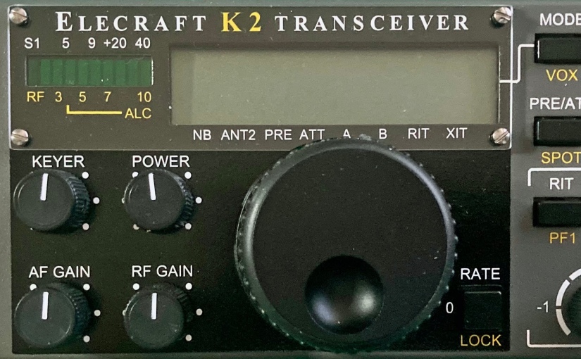
The Front Panel Board is where all of the user controls are mounted. These include the large rotary encoder/tuning knob, the numeric keypad and pushbuttons, and five variable resistors. This section also includes the graphical LED status bar display and the LCD main display.

Assembly of the front panel starts by soldering the sixteen tactile push button switches to the printed circuit board. For a proper and neat professional appearance, it’s essential that all of the switches be mounted at a precise uniform distance from the surface of the board.

Elecraft provides a nifty switch spacing tool in the kit which is essentially a thin narrow bit of PCB material that is placed under each switch which is then pushed flush to the spacing tool. This clever method worked exceptionally well for me.

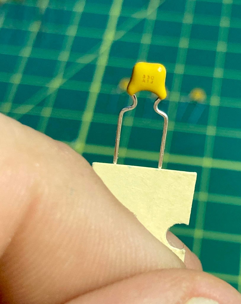
After the switches are mounted, the board is populated with the usual components – resistors, capacitors, diodes and transistors. The front panel board has four ICs including the large 40 pin U1 which is mounted on the bottom side of the board and behind the display.

The front panel board also has a good bit of hardware to be attached including the eight-pin microphone jack and several spacers. Up to this point the instruction manual has been absolutely excellent in providing detailed easy to follow accurate directions.

However, I did encounter some difficulty when it came to mounting the main display components which consists of two backlight LEDs, their spacers, a white cardboard reflector, a frosted plastic diffuser, and the 40 pin LCD.

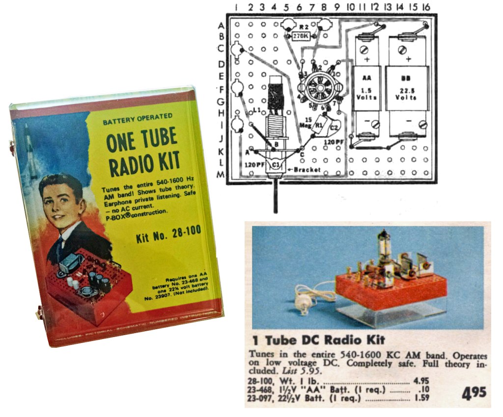
As I discussed in my previous post, the Elecraft K2 is a fabulous kit, but it’s a rather old kit, first prototyped a quarter century ago – in 1997! Understandably in the time since its introduction, some components become ‘unobtainium’ as the years go by. Vendors come and go and with advancing technology, manufacturers discontinue production of now archaic through-hole components with today’s increasing popularity of SMD architecture.

Thus, when one buys a K2 kit today, it will come with several pages of errata that must be carefully consulted and reviewed. Builders in 2022 will find themselves crossing out sections, sometimes whole pages, of the original manual, and adding notes about the replacement modern components packaged with their kit.

This was the case with the display assembly. I was instructed to cross out most of the directions pertaining to the installation of the display on pages 27 and 28 of the manual and to follow the alternative directions provided as errata.

The revised directions call for the builder to first insert the leads of a pair of rectangular LEDs through plastic spacers and solder the LEDs flush to the board to the left and the right side of where the LCD will be mounted.

Between the two LEDs, the builder places a white cardboard backlight reflector and then mounts a frosted plastic diffuser by placing it over the the two LEDs on the left and the right side. The diffuser has an indent on each side to accomondate the LEDs.

I found this all went precisely as described until I came to the step that instructed me to place the LCD flush on top of the diffuser and then solder the 20 pins of the LCD to the associated pads on the PCB.

None of the LCD pins were long enough to go through the holes in the pads on the board. If pressed flush to the diffuser the LCD pins just barely touched the pads.

With the LCD flush against the frosted crystal diffuser, the pins are too short to penetrate the holes in the pads.
A view of the bottom side of the board showing the inadequate length of the LCD pins.

I carefully checked the instructions and my work. I was certain I mounted the LEDs correctly and flush to the board with their spacers, and the cut outs on the bottom side of the plastic diffuser neatly accommodated the LEDs perfectly.

Realizing that proper positioning of the LCD would be critical for the PCB to properly fit in the front panel and knowing that not getting the spacing correct would also give the finished radio a sloppy appearance, I reached out to Elecraft for help via their website.

I dreaded the prospect of having to de-solder 20 pins and run the risk of damaging the LCD if I needed to remove it after it was soldered in place. I wanted to get as much information as I could before proceeding.

I received an email reply from Dave at Elecraft who is their K2 support guy within a couple of days. Dave stated that it was ‘perfectly normal’ for the LCD pins to just touch the top pads on the PCB and that they do not need to protrude through the holes. He said that his last K2 build was like this and suggested that I carefully solder the 20 pins from the topside, but to make sure the LCD is level and parallel to the board.

I did as Dave recommended, carefully aligning the LCD so it was level and evenly spaced above the board. I started by soldering each of the corner pins and confirming the LCDs position after each solder joint. Once done, I applied solder to the pads on the bottom of the board to let it flow through the hole to help ensure solid contact.

However, after I soldered just under half of the LCD pins, I realized I had left out the cardboard reflector. D’oh! There was no way I could slide the stiff cardboard under the pins at this point and I didn’t want to have to de-solder so many pins, so I came up with a workaround.

I took a piece of white copier paper and cut a rectangle to the same size as the cardboard reflector. Cutting the paper in half, I was able to slip both halves between the gap in the pins on the bottom of the LCD and position them in proper place. I held them in place with a bit of cellophane tape.

From here on out the rest of the front panel assembly went smoothly. Again I encountered the need to reference the errata for the main encoder knob as Elecraft includes a different unit than the one referenced in the original instruction manual. The encoder in my kit required me to solder a few parts into an auxiliary board to which the encoder was attached. The auxiliary board is then attached to the back of the front panel board.

The rotary encoder auxiliary board.

The last step was to mount the completed front panel board inside of the front panel. Before doing so, the manual lists about 30 resistance checks for the board. Each test point checked out as specified to ground – excellent!

I was very pleased that after I carefully mounted the board the front panel looked perfect. All of the push buttons were a proper and uniform height through the holes on the panel. All knobs, including the main encoder dial, were also correctly mounted and turned with ease. Best of all the main display LCD that caused me so much grief, looked perfect under the front bezel.

Completed Front Panel PCB, front.
Completed Front Panel PCB, back.
The completed front panel…. it ‘looks’ like a radio anyway.

Next up – the RF Board. Stay tuned….

Elecraft K2 Build – Part 1

Control Board Assembly

As the proverb goes, a journey of a thousand miles begins with a single step. So, after procrastinating for two plus years after my XYL and soulmate Ellen gifted me the Elecraft K2 HF Transceiver Kit for our tenth anniversary, I finally got my nerve up to start what will easily be my most ambitious kit build ever.

It is my intent to blog about my experience as I proceed, circuit board by circuit board, sharing my experience and inviting others who have built the K2 to share as well.

The Control Board

Having set up and outfitted a new protected work bench using a folding banquet table in the shack where I will work only on the K2, I started work on the first circuit board, the Control Board on January 9, 2022.

As with many kits I’ve built, the Elecraft instructions call for the builder to start by inserting and soldering all of the fixed resistors first. As others have reported, I found the instructions to be, for the most part, very well written. The instructions for the fixed resistors provided each resistor’s value in ohms as well as the color code and the builder is encouraged to install the resistors with the first color band towards the top or the right of the circuit board to facilitate verifying the correct resistor is in the correct space when reviewing or troubleshooting your work.

As electronic components have gotten increasingly smaller, my vision has gotten progressively worse as I’ve gotten older. Whenever kit building, I always verify values with my VOM before inserting any resistors into a circuit board. After installing the 13 resistors, the instructions called for the installation of seven resistor arrays and one trimmer pot, all easily identified.

The Control Board after installing all resistors.

Next the builder needs to install an 82 mH inductor, which I confirmed I had the correct part with my L/C meter, followed by a pair of silicon diodes. I then encountered the first variation in my kit. Where the original PCB had a screened space for D3, the instructions called for an 82K ohm resistor to be installed here.

The instructions next call for the builder to install and solder in place 36 fixed capacitors. Identifying and verifying the value of each capacitor was a notable challenge. Not only were the stamped or printed values on the caps miniscule, the capacitors also varied in type, shape, and manufacturer and it was clear that some of Elecraft’s suppliers changed over the twenty-five years they have been offering the K2 kit, as some of the caps did not match in appearance to the identifier pictures in the otherwise excellent parts list in the appendix.

To guarantee I placed the correct capacitor in the correct space, I took the time to identify every capacitor and laid them out neatly on my workbench in the same order the instructions called for their installation.

To identify the values, I used the camera on my iPhone and zoom in on the part. Sometimes when the value is etched on the capacitor, I needed to shift it so my bench light catches the labeling just right to read. I took the time and used my L/C meter to verify the value of every capacitor.

Once all of the capacitors were laid out in the order of installation, I carefully installed each capacitor into its space, having taken the time again to double-check values with the L/C meter. It was a slow process, but in the end, I felt very confident all of the capacitors were soldered in the correct space giving me peace of mind. Trouble shooting for mis-placed capacitors would be a very tedious process if necessary.

The next several steps went along easily as I installed the electrolytic capacitors, a trimmer cap, a dozen bipolar junction transistors, a pair of crystals, two voltage regulators, one IC socket and various connectors. All of these parts were easily identified, and when working with the transistors, I proceeded in the same manner as I did with the fixed caps, identifying and verifying value, arranging them in the order of installation and double-checking values as I installed each.

The bipolar transistors, values checked and laid out in order of installation.

Now it was time to install the ICs on the control board, and this is where I first ran into trouble.

The very first chip was an NE602, the AGC mixer. I mentioned that the K2 has been on the market for twenty-four years and over the course of a quarter century, technology moves on and the availability of parts change. By the time Elecraft had kitted my specific K2, the NE602 was no longer widely available in through-the-hole DIP casing. The industry had since begun moving on away from through-the-hole components in favor of tiny, less expensive surface-mount versions.

Instead of the DIP version of the NE602, my kit came with an equivalent SMD NE612 which was pre-soldered to a small square ‘carrier board.’ The carrier board is a PC board cut to the same footprint of an 8 pin DIP case and the builder is instructed to cut eight 1-inch pieces of wire, insert them into the eight holes on the carrier board, solder them in place, then insert the bottom ends of these wires through the DIP-spaced holes and solder to the control board.

I damaged the carrier board while attaching the wires by working sloppily with a too-hot iron. The carrier board was not of the same high quality as the control board which featured double plated holes. The carrier board had plating only on the top of the holes, and I managed to lift the plating off of the number 2 and number 3 hole, breaking connectivity. I tried to bridge the contacts to the chip contacts with a solder blob, but that only made a bigger mess of things.

Elecraft has a form on their website to order replacement parts and I reached out on January 1qth to inquire about purchasing a replacement NE612 and carrier board. I did receive an acknowledgement that they received my inquiry from a mail bot, but as of this writing, four days later I have not received an actual reply.

In the meantime, I began wondering whether I could still find DIP cased versions of the NE602 elsewhere online. I searched Mouser, Digi-key, eBay and Amazon and found that an Amazon vendor had some available, which I ordered. The vendor did not disclose the name of the manufacturer nor the source country, but I’m assuming the chips were manufactured in China. I did order five (there are three others elsewhere in the K2) and they arrived within a day or two.

I discussed my dilemma with one of my Elmers, Steve, KZ1S, who has built many a kit in his day and is a physics professor who works with electronic circuits and RF in his work.

Steve offered a couple of suggestions. The first was to use a proper SMD to DIP converter board with proper pins spaced correctly. I liked this idea very much, but the drawback is that it would require me soldering the SMD chip to the converter board and again, with my failing vision and dexterity, this would be a bit of an unpleasant challenge.

A proper SMD – DIP converter

Steve also suggested looking for genuine NOS chips online, either on eBay, or from Radwell International. Steve mentioned you can source just about any obsolete part with Radwell, but they can be expensive. I did locate the NE602s on there with a retail price of about $5 – not a deal-breaker, but given I need four for the K2, that’s an additional $20 + shipping.

For the time being, I decided to place a DIP socket on the control board and once in place, I inserted the NE602 of dubious origin I purchased from Amazon in the socket. For the time being this would let me continue with the build and be able to test resistances. I could then swap out the AGC chip for a genuine NOS or SMD + converter at a later date.

I finished the build of the control board this morning, directly soldering in the remaining ICs and adding the two CW key-shaping capacitors on the solder side of the board.

After carefully double-checking all of my work, I used my VOM to perform the resistance checks. All of my test resistances were within range, excepting U6 pin 29 (DASH) and U6 pin 30 (DOT/PTT) which were marginally over spec. The acceptable range for both is 70K – 90K ohms and I measured 96.6K on pin 29 and 96.8K on pin 30. I will revisit these values later.

So that concludes the build of the first circuit board, the Control Board. I counted a total of 110 components soldered to the board and I completed the work in eight days working at my deliberately leisurely pace.

I welcome comments and suggestions from any and all, particularly from anyone who has built the K2 and had to deal with the SMD carrier board themselves. Drop me a line at james@ab1dq.com to share your thoughts and opinions.

Next up – the Front Panel Board – stay tuned!

Elecraft K2 Build – Introduction

I built my first electronic DIY kit when I was about 10 years old. Dad brought home the Radio Shack One-Tube AM receiver P-Box kit and we spent the better half of the following Saturday at the workbench in the basement building it together.

It was an amazing formative experience – spending the day working on the project with dad, learning about the various electronic components and how they worked in the circuit, and getting my first try at soldering.

I treasured the completed radio and can vividly recall that magic moment when I first clipped the ground wire to an exposed gas pipe behind the parlor stove, sticking the hard plastic crystal earpiece in my ear and tuning the loopstick and hearing WBZ in Boston coming in loud and clear on the radio dad and I built out of a handful of parts.

This was the first of many Scie`nce Fairâ„¢ P-Box kits I would build throughout my early teen years. No Christmas or birthday was complete without one (or two!) new kits. I remember building the organ, the two-transistor AM radio, the “GoofyLight,” the indoor/outdoor electronic thermometer, the moisture detector, the AM Wireless microphone and the frequency standard.

My first kit build – the Science Fair ONE TUBE RADIO KIT,
sold by Radio Shack circa 1974

I was hooked on kit-building and at some point, in my teen years I saw my first Heathkit catalog and was blown away at the more complex scale and wide variety of Heathkits… radios, hi-fi gear, test equipment, computers, even television sets. I began setting my sights on taking my kit-building to the next level.

However, in the mid- to late- eighties my focus and all of my earnings went into getting through college. By the time I had the time and disposable income to return to the kit-building workbench, the Heathkit era was sadly over.

At the turn of the century, I was in the position to have the time and money to return to my radio and electronics hobby. In 2002 I earned my amateur radio license and from the get-go started building ham-radio related kits. These included receivers and QRP transmitters and a variety of accessories like tuners, station clocks, sold by kitters such as Oak Hills Research, Four State QRP Group, MFJ, Small Wonders Lab, TenTec, and Rex Harper (QRPMe), among others. These were fun builds and there is nothing like using gear you built to make contacts on the air.

However, even the best ham gear I built still fell short of having built and having a showpiece full feature 100-watt multi-mode transceiver like the venerable HW101 in my shack.

The Heathkit HW101 `100-watt 10-80 m transceiver

In 1998, Elecraft, a new retailer of amateur radio gear was founded in California by Wayne Burdick and Eric Swartz with the introduction of their first product, the K2, an HF transceiver that could be purchased as a kit or fully assembled.

The K2 features dual VFOs with multiple memories, split TX/RX operation, RIT/XIT, full break-in CW, memory keyer, narrow IF crystal filtering, and IF derived AGC and the base radio can be built as a 5-watt QRP CW rig with optional accessory boards available to add SSB and amplify the RF output to a full 100 watts.

Initial reviews by the ARRL and other professional publications as well as those written by amateurs who have built and operated the K2 were excellent. The consensus was that the K2 has become a worthy choice for builders lamenting the disappearance of Heathkit. Reviews cited that the Elecraft kits were well packaged, completed, and the instruction manuals and documentation provided was detailed and easy to follow – not unlike the Heathkit manuals of a prior generation. Elecraft also got high points in published reviews for excellent customer support.

A bit over two years ago, my wife Ellen gave me the K2 kit, along with the 100 watt amplifier board and the SSB board as a gift for our tenth wedding anniversary. (I frequently point out that no man ever married better than I!)

Although I wanted to build the K2, and indeed put it on my gift ‘wish list’ – I let it sit in the workshop for over two years! I knew the project would take months on end to complete, and in order to succeed I would need to maintain a clean workspace, take my time and work slowly and diligently.

I think I have many fine qualities, but I’d be the first to tell you attention to detail and neatness are not among them. I was further intimidated by the fact that electronic components have gotten smaller while I have gotten older. My vision, which was always poor from birth, wasn’t getting better and my hands are starting to get a little shaky.

I finally resolved as we headed towards 2022 to tackle the K2. I created a new ‘protected’ workspace in my shack/mancave, moving in a folding banquet table, topping it with a pair of self-healing cutting mats and setting up my magnifier lens, solder station, some essential hand tools and my VOM, capacitance/inductance meter and my laptop.

The bigger resolution was to keep this space protected and clean. I resolved to not let this space become cluttered. I would not place anything not Elecraft related on this dedicated workspace, and I also resolved to clean up the space every time I stopped work, making sure I didn’t leave any loose parts out.

HIYA SMOOOOOOOOOSHIE!
Cats don’t understand ‘protected workspace‘ nor do they care that much.

And with all that in mind, I finally started my build this month and my intent is to blog about the experience here and intend to blog as I complete each board. I invite you to join me for the journey. I hope those who have already built the K2 reach out with comments, tips and tricks – any input will be most appreciated. I also hope that this blog may be a resource or an inspiration for other builders.

Please feel free to leave a comment or write to me at james@ab1dq.com.

Thanks for stopping by!