

INTRODUCTION & CONSTRUCTION
The Four State QRP Group (Oklahoma – Kansas – Arkansas – Missouri, in case you were wondering), founded in 2003, is one of the best developers and retailers of high quality and reasonably priced QRP (low power) ham radio and other do it yourself electronics kits.
I have a few of their kits over the past few years, most recently including the Bayou Jumper Paraset transceiver last year. I presently have the NM0S 4S-Tuner/Antenna Coupler kit on order.
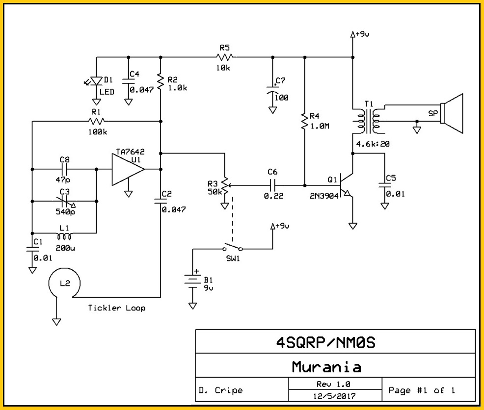
Tonight I tackled one of their popular new non-ham radio kits, the Murania, a one transistor Tuned Radio Frequency (TRF) AM broadcast band receiver kit. The kit was designed by NM0S, David Cripe, who has engineered several of the 4SQRP kits.
The documentation for the Murania tells of the advent of transistor radios in the 1950s and how radios with 1 or 2 transistors were considered toys and therefore not taxed like radios containing more transistors. These 2 or less transistor “toy” radios became known as “Boy’s Radios” and are highly collectible today.
The designers of Boy’s Radios employed some creative design techniques to maximize the performance of these minimalist circuits, with sometimes amazing results. The Murania kit was inspired the design of those simple high performing transistor radios.

My Murania kit arrived quickly within 2 days of placing my order online….WOW!
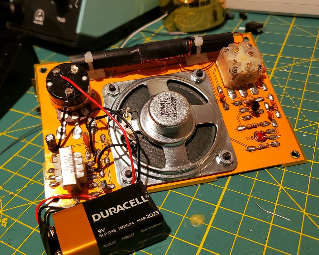
The Murania features a unique construction technique called “Pittsburgh Construction” developed by W0MQY , Joe Porter, in which components are soldered to the surface of pads on a silk screened double sided PCB.
Like other 4SQRP kits, the assembly manual needs to be downloaded from their website. Documentation is very good with clearly expressed step by step directions, but lacks pictures which might be helpful in illustrating potentially confusing steps for the newbie builder, such as the correct orientation of a polarized component such as an LED, diode or electrolytic cap.
The 4SQRP website suggest the kit can be built in about 2 hours time, and that was my experience. The radio is built in five stages… (1) wind the coil, (2) build the voltage regulator, (3) build the audio amp, (4) build the RF circuit, (5) final assembly.
1. Winding the Coil
The first task is to wind the coil which consists of 37 turns of No. 22 AWG enamel wire around a ferrite core. The instructions call for covering the core with a layer of masking tape first and using masking tape to hold the first and last winding in place.

winding the coil.
I chose to use black electrical tape, and that was definitely a mistake – the electrical tape made it difficult to compress each winding snug against the previous winding and it didn’t do a very good job of holding the first and last winding in place.
I believe this may have also affected performance of my radio (see below). I am planning on modding the set and rewinding the coil with 61 turns (also, see below) and will use the recommended masking tape at that time.
2. Voltage Regulator
The first circuit constructed is the power supply/voltage regulator which consists of installing the volume control pot and attached power switch, one electrolytic capacitor, the battery connector, another capacitor and a resistor and the LED which serves three functions – power on lamp, signal strength indicator, and voltage regulator delivering 1.6 – 1.8 +VDC to power the radio.

I appreciated that the instructions called for testing the voltage regulator circuit before proceeding on to the audio amp stage. My Murania was putting out 1.792 VDC+ within the acceptable range of 1.6 – 1.8 volts.
3. Audio Amplifier
The Murania has a single stage of audio amplification based on the 2N3904 NPN transistor that drives the speaker through a matching transformer.
Other components in the stage included a pair of capacitors, a single resistor and of course, the transformer and speaker.
4. RF Stage
The bulk of the RF work is handled by a single IC, the TA7642, which has its origins in the late 1960s. Equivalent to the ZN914 and MK484, the TA7642 contains ten transistors and performs the task of RF amplification, audio detection, and automatic gain control. The documentation points out that with the TA7642, it is possible to construct a Tuned Radio Frequency receiver with useful sensitivity and selectivity, using only a handful of components and that this device served as the basis of many radio receivers that were the successors to the Boy’s Radios.

Like the voltage regulator and audio amplification stages the RF stage went together without a hitch. All parts in the kit were properly identified and clearly referenced in the assembly manual. The etching on the circuit board made mis-installation pretty much an impossibility if you’re paying attention to what you’re doing.
5. Final Assembly
After testing the radio to make sure it works (it did), the last step was to assemble the rest of the cabinet which is comprised of five additional pieces of yellow PCB material with pads strategically placed to match up for soldering to connect.
The pieces fit together perfectly, although I should have taken time as recommended in the directions to file off burs and rough spots so the pieces fit together more perfectly. Overall this is a pretty ingenious way to build a radio cabinet.
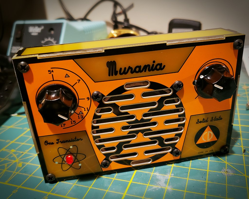
THE FINISHED PROJECT – IT WORKS!
PERFORMANCE AND MODS
I was very pleased that the radio worked right away. I was able to pick up several AM stations with ease. Stations received were clear and the audio, while not as loud as I would have liked, was not distorted.
One problem I did encounter that is worth mentioning is that after I tested the radio on my bench I attached the back to the radio and brought it to my wife to show off my handiwork.
She was impressed, however when she turned the radio on, the LED lit up but there was no sound coming from the speaker – absolute silence – UGH!
I took the back off and quickly diagnosed the problem – the top of the 9V battery was shorting the speaker terminals – a problem easily fixed with a piece of electrical tape across the speaker terminals.
I did expect the radio to be a little more sensitive than it was initially and I realized that the radio’s performance might have been inhibited by my sloppy coil winding.
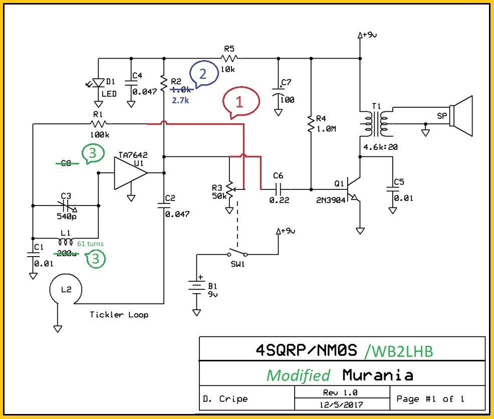
Online I found a list of three simple mods for the radio published by Jim Marco, WB2LHP in MI, the third of which that involves additional windings on the coil so I thought I’d give them a try.
Here are Jim’s mods…
1. Detector Gain Control…
FLOAT the wiper lug of R3 and place a jumper between the PADS for the R3 wiper and the high side of R3.
Lift the leg of R1 that intersects with R2 and R3 and connect a jumper between the floated leg of R1 and the wiper of R3.
According to Jim, this allows R3 to control the gain of the detector stage in the TA7642 acting similar to a regen control where there is both volume and gain reaction. The audio amp runs wide open and R3 should be adjusted for the best sounding audio.
2. Reduced audio distortion…
Changing R2 from 1K to 2.7K biases the output stage of the TA7642 for linear operation.
3.Frequency coverage and dial mapping…
Increasing L1 from 37 turns to 61 turns and removing C8 centers the frequency coverage and makes the dial tracking spot on…
I am pleased to say that the mods were easy to accomplish and I had no difficulty with any of them. I did not have a 2.7K ohm resistor on hand so I tied a 2.2k and a 470 ohm resistor in series for R2. Using the recommended masking tape instead of rubbery electrical tape on the ferrite rod made a world of difference too – winding the 61 turns was a snap.

And how did it work? Even better than before – the radio seems to be more sensitive and is picking up more stations and the audio is definitely more crisp as promised. If you’re looking for a fun one-evening project that will take you back to your earlier days of melting solder – the Murania TRF receiver is worth building.
©2019 JMSurprenant

The 2.7K change for R2 didn’t work for me. It left the TA7642 biased off, so no output. I tried the original 1k, and it came to life, but was very unstable. I ended up with 1.8K, which works very well. I didn’t try other values, so experimentation is always worth a try. Dick, W9ZB
LikeLike