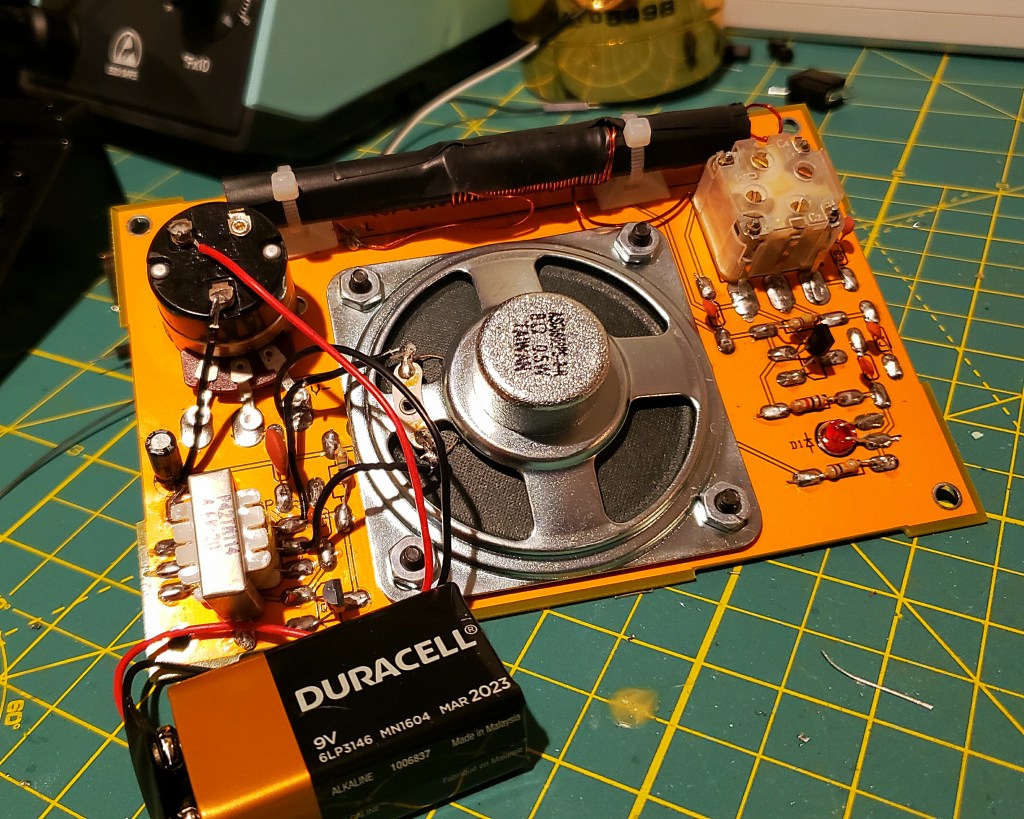
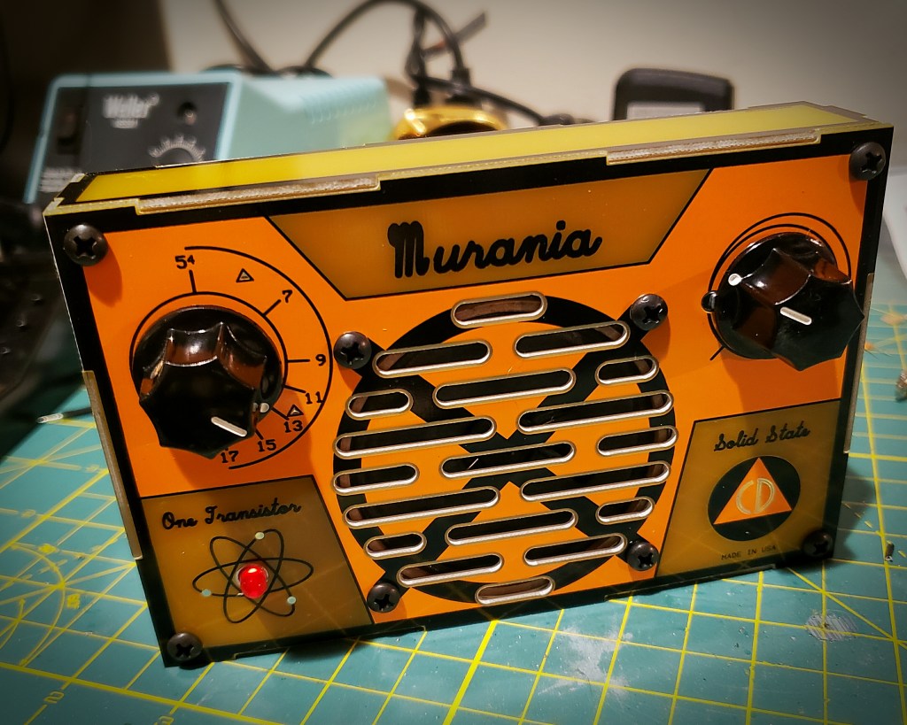
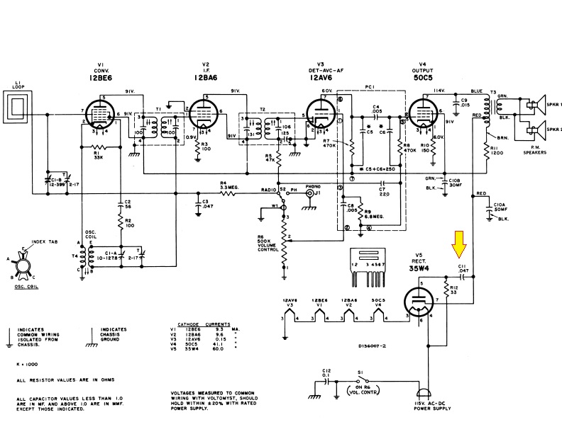
I built my first electronic DIY kit when I was about 10 years old. Dad brought home the Radio Shack One-Tube AM receiver P-Box kit and we spent the better half of the following Saturday at the workbench in the basement building it together.
It was an amazing formative experience – spending the day working on the project with dad, learning about the various electronic components and how they worked in the circuit, and getting my first try at soldering.
I treasured the completed radio and can vividly recall that magic moment when I first clipped the ground wire to an exposed gas pipe behind the parlor stove, sticking the hard plastic crystal earpiece in my ear and tuning the loopstick and hearing WBZ in Boston coming in loud and clear on the radio dad and I built out of a handful of parts.
This was the first of many Scie`nce Fair™ P-Box kits I would build throughout my early teen years. No Christmas or birthday was complete without one (or two!) new kits. I remember building the organ, the two-transistor AM radio, the “GoofyLight,” the indoor/outdoor electronic thermometer, the moisture detector, the AM Wireless microphone and the frequency standard.
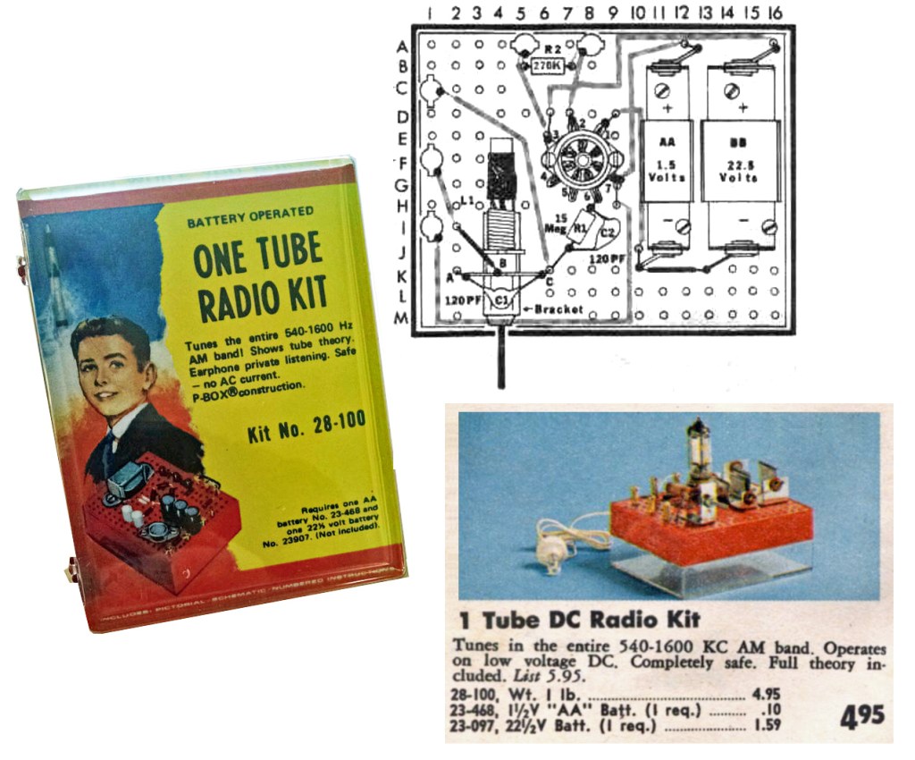
sold by Radio Shack circa 1974
I was hooked on kit-building and at some point, in my teen years I saw my first Heathkit catalog and was blown away at the more complex scale and wide variety of Heathkits… radios, hi-fi gear, test equipment, computers, even television sets. I began setting my sights on taking my kit-building to the next level.
However, in the mid- to late- eighties my focus and all of my earnings went into getting through college. By the time I had the time and disposable income to return to the kit-building workbench, the Heathkit era was sadly over.
At the turn of the century, I was in the position to have the time and money to return to my radio and electronics hobby. In 2002 I earned my amateur radio license and from the get-go started building ham-radio related kits. These included receivers and QRP transmitters and a variety of accessories like tuners, station clocks, sold by kitters such as Oak Hills Research, Four State QRP Group, MFJ, Small Wonders Lab, TenTec, and Rex Harper (QRPMe), among others. These were fun builds and there is nothing like using gear you built to make contacts on the air.
However, even the best ham gear I built still fell short of having built and having a showpiece full feature 100-watt multi-mode transceiver like the venerable HW101 in my shack.

In 1998, Elecraft, a new retailer of amateur radio gear was founded in California by Wayne Burdick and Eric Swartz with the introduction of their first product, the K2, an HF transceiver that could be purchased as a kit or fully assembled.
The K2 features dual VFOs with multiple memories, split TX/RX operation, RIT/XIT, full break-in CW, memory keyer, narrow IF crystal filtering, and IF derived AGC and the base radio can be built as a 5-watt QRP CW rig with optional accessory boards available to add SSB and amplify the RF output to a full 100 watts.
Initial reviews by the ARRL and other professional publications as well as those written by amateurs who have built and operated the K2 were excellent. The consensus was that the K2 has become a worthy choice for builders lamenting the disappearance of Heathkit. Reviews cited that the Elecraft kits were well packaged, completed, and the instruction manuals and documentation provided was detailed and easy to follow – not unlike the Heathkit manuals of a prior generation. Elecraft also got high points in published reviews for excellent customer support.
A bit over two years ago, my wife Ellen gave me the K2 kit, along with the 100 watt amplifier board and the SSB board as a gift for our tenth wedding anniversary. (I frequently point out that no man ever married better than I!)
Although I wanted to build the K2, and indeed put it on my gift ‘wish list’ – I let it sit in the workshop for over two years! I knew the project would take months on end to complete, and in order to succeed I would need to maintain a clean workspace, take my time and work slowly and diligently.
I think I have many fine qualities, but I’d be the first to tell you attention to detail and neatness are not among them. I was further intimidated by the fact that electronic components have gotten smaller while I have gotten older. My vision, which was always poor from birth, wasn’t getting better and my hands are starting to get a little shaky.
I finally resolved as we headed towards 2022 to tackle the K2. I created a new ‘protected’ workspace in my shack/mancave, moving in a folding banquet table, topping it with a pair of self-healing cutting mats and setting up my magnifier lens, solder station, some essential hand tools and my VOM, capacitance/inductance meter and my laptop.
The bigger resolution was to keep this space protected and clean. I resolved to not let this space become cluttered. I would not place anything not Elecraft related on this dedicated workspace, and I also resolved to clean up the space every time I stopped work, making sure I didn’t leave any loose parts out.

Cats don’t understand ‘protected workspace‘ nor do they care that much.
And with all that in mind, I finally started my build this month and my intent is to blog about the experience here and intend to blog as I complete each board. I invite you to join me for the journey. I hope those who have already built the K2 reach out with comments, tips and tricks – any input will be most appreciated. I also hope that this blog may be a resource or an inspiration for other builders.
Please feel free to leave a comment or write to me at james@ab1dq.com.
Thanks for stopping by!