
One of the now defunct electronics kitters, whose products I personally appreciated ‘back in the day,’ was Ramsey Electronics.
Ramsey, which still exists as a firm today, but no longer sells electronic kits, produced a fairly expansive line of straight forward do it yourself solder kits that were not too complicated for the new to intermediate builder, and that came with exceptional documentation which not only provided the builder with detailed step-by-step instructions, but also included information on circuit theory explaining why and how it worked, and what the sub-circuits and individual components did. Often included were suggestions for kit mods, sometimes as provided by previous builders of the kit. Their motto was “Build It, Learn It, Achieve It, and Enjoy It!“

After providing great kits to the electronics hobbyist community for more than four decades, Ramsey shut down its kit division in 2016 and has been sorely missed by hams and other electronics hobbyists ever since. Today the occasional unbuilt Ramsey kit will appear at local hamfests and on eBay, so if you’ve never had the experience of building a Ramsey kit, there’s still a bit of hope for you. For an appreciation of the breadth of their kit offerings, you can browse of one of their catalogs here.
Building a 90’s era Ramsey Kit – the QRP20 CW Transmitter
Recently, after coming across the Ramsey Active SW antenna kit I built back in the 90s, before I earned my ham ticket, but was an active shortwave listener, I found myself feeling nostalgic for the Ramsey kit experience and found an unbuilt 20 meter transmitter kit on eBay. When the auction ended four days later my bank account was $32 lighter and I found myself eagerly waiting for my new kit to arrive.
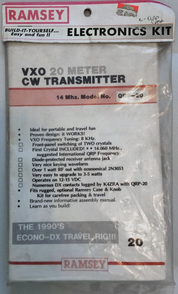
The QRP20
The kit promptly arrived a few days later, well packaged, and just as described. I was happy to see that it was unopened and complete. My winning lot included not only the QRP20 transmitter kit, but also the matching plastic case complete with pre-drilled and labeled front and back panels.
Given my recent obsession for building ham gear into cigar boxes, I planned to skip the signature Ramsey case but I realized the pre-drilled front and back panels would make an excellent template for drilling out my cigar box cabinet.
The QRP20 enjoyed favorable reviews on eHam Product Reviews with a solid four out of five stars average rating. Common among the reviews were observations that the transmitter was easy to assemble and had no drift or chirp. Several builders commented they had upgraded the cheap driver and amp Q2 and Q3 that shipped with the kit for more robust transistors for increased RF output.
The QRP20 is specified to put out 1.0 watts of RF power drawing 1/4-amp current from a 12-15 VDC source and it has two unique features to set it apart from competitors’ offerings.
The first is a space on the PCB to install a second crystal or to wire in a crystal socket. The second frequency, or socket, is selected by a pushbutton on the front panel. Ramsey included a single 14.060 crystal with the kit and leaves it to the builder to use the second crystal slot to accessorize as he desires. (I plan to add a crystal socket myself.)
The other welcome feature is the QRP20’s built in T/R switch – a nice bonus feature that will make for easy mating to the matching Ramsey HR20 DC receiver or any other QRP receiver.
Ramsey offered the QRP20 for many years and over that time, the circuit was tweaked, the instruction manual was updated, and eventually some parts were substituted for others.
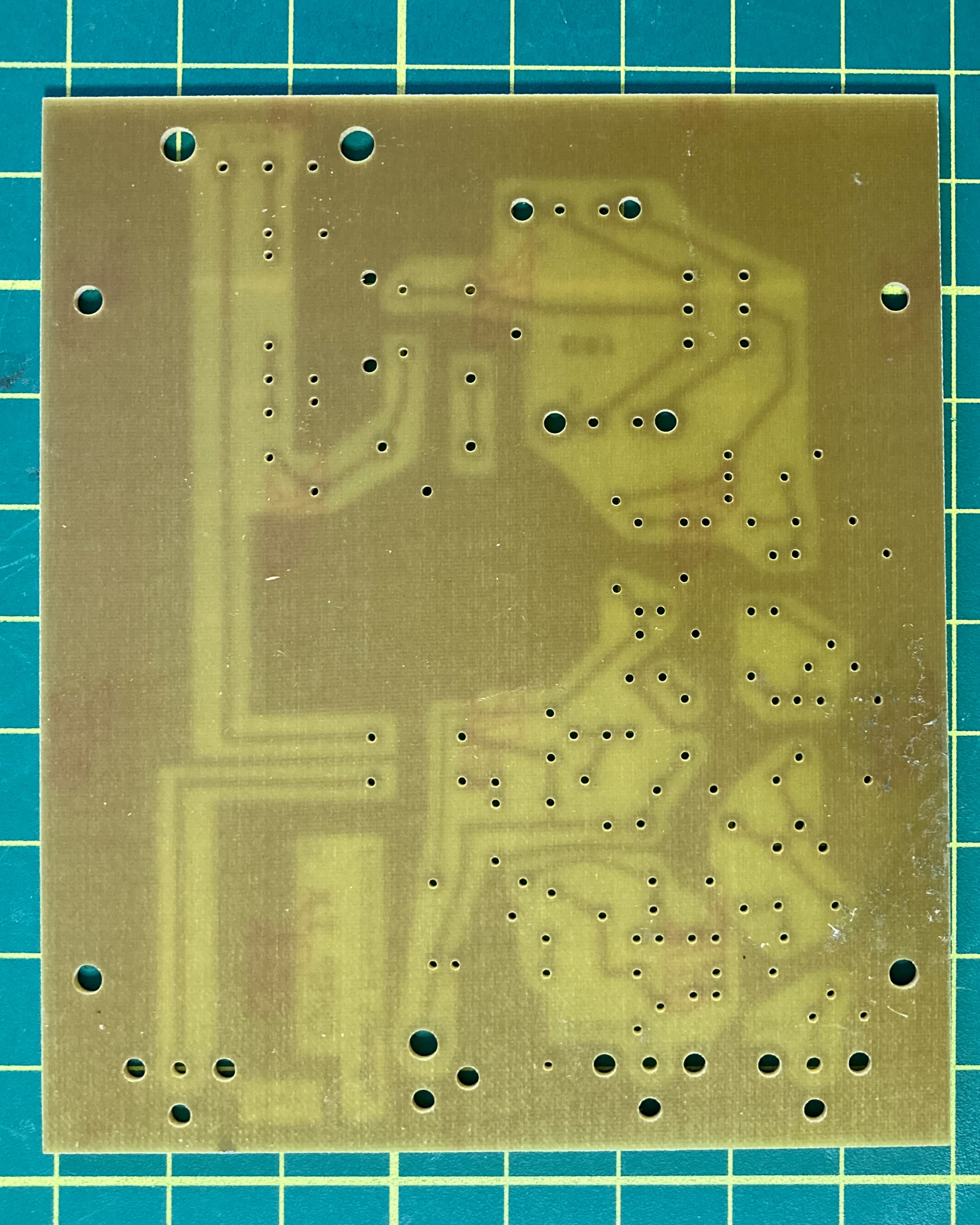
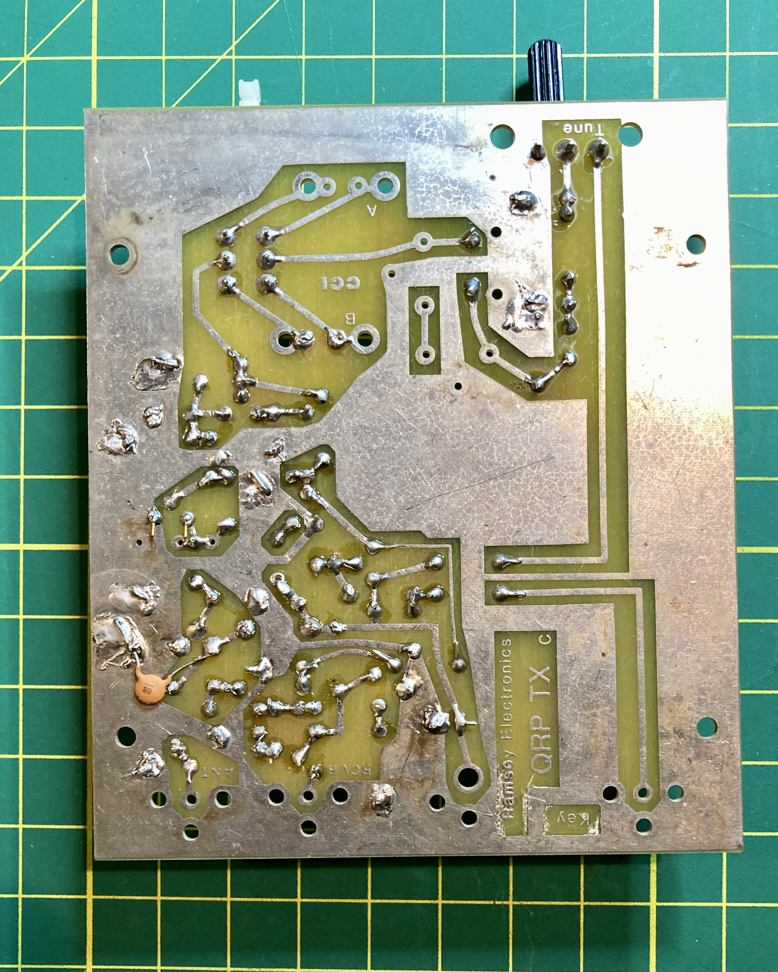
The manual in my kit was copyright 1990 and in addition to the manual, the kit included a large separate fold out parts finder diagram of the circuit board. This was most useful as this generation of the QRP20 PCB did not include screening on the component side showing individual part layout. With the Parts Finder diagram laid out on my workbench I had no difficulties identifying where every component belonged.

Assembly took about 2 hours over 3 sessions. I tend to work slowly and deliberately when kit building, and I’m a big proponent of the adage, measure 2x, cut once. In kit building, I tend to identify/measure component values thrice, solder once.
I mentioned above that over time, Ramsey modified the circuit and also some components were changed, most likely due to changing availability from suppliers. I encountered a couple of these changes in my build – all of which involved the inductors – which required a bit of extra caution on my part.
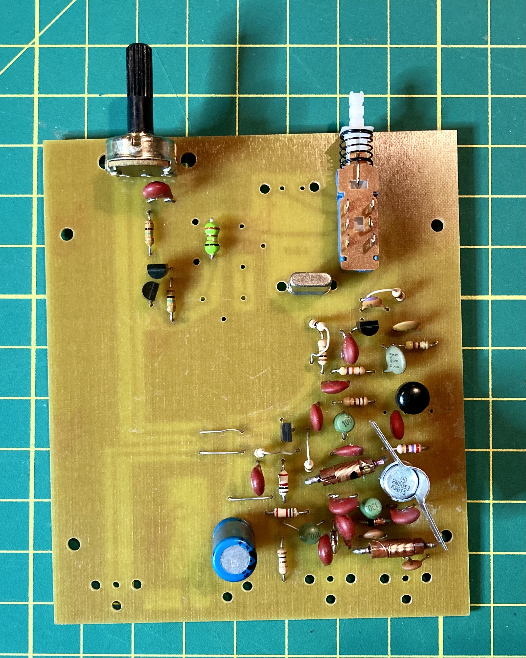
First, the Parts Finder showed a square footprint for L1, an inductor with a tuning slug. The diagram labeled it as L1 40M, with two arrows pointing to where the solder points were for the inductor. The 20-meter version of the kit that I was building, included an axial inductor with no tuning slug, the type that looks like a resistor complete with color-code bands.
The parts list stated that L1 for the QRP20 may have been either a 2.2 uH or a 3.9 uH inductor. I was able to confirm that my kit included a 2.2 uH inductor by the red-gold-red color code, and I verified the value with my L/C meter.
Inductors L2, L4, and L5 presented a bit of a challenge too. Every printed reference to these 3 inductors in the manual stated they were 220 uH and the parts list on page 20 described them as molded brown with red stripes. There was no mention in the printed instructions that the kit may have included an alternative set of inductors with different values for L2, L4 and L5. However, on the page 20 parts inventory was a parenthetical hand-written statement under the printed entry for these inductors which read “or 100uH -green 100.” There were three beehive shaped green components with a ‘100’ stamped on the top, so I felt confident these were L2, L4 and L5.
Lastly, L3 and L6 were 1.0 uH inductors but neither the instruction manual nor the parts inventory described their appearance or markings. I found two wire-wound inductors in the parts bag but they had no color code or printed markings and they were too long to easily fit in the matching holes on the PCB. But by process of elimination, I concluded these were L3 and L6 and again I confirmed their value with my L/C meter. I needed to use extra caution to carefully bend the leads 180 degress, back under the inductor body, and then 90 degrees again through the PCB holes.
The only other construction issue worthy of mentioning is the special care I took take to properly identify the leads for the four bipolar transistors. While the Parts Identifier diagram had a circular outline for each transistor with a flattened side, it did not label any of the holes as B, C and E. I connected each transistor to my transistor tester to identify the base, collector and emitter, drew a diagram in my notebook to keep the terminals straight and then cross referenced my sketch with the the schematic and Parts Layout to make sure I got these right. Having to resolder transistors after I snipped the excess leads would be a pain.
Cigar Box Considerations and Mods
I chose a nice small Nub cigar box for my QRP20 cabinet. The cigar box dimensions were 6 1/4″ x 4 7/8″ x 2 1/2″ which meant it should nicely accommodate the Ramsey 4″ x 4 3/4″ PCB. My plan was to mount the circuit board to the bottom of the cigar box and drill out holes on the front of the box to accommodate the tuning potentiometer and the crystal selector push button switch. The meant with careful drilling, I could mount both the pot and the switch direct to the PCB as Ramsey intended and have them poke through properly aligned holes in the front of the cigar box.
However, the depth of the box was a bit too long, which meant the rear connections soldered to the circuit board (antenna, receiver null, power connection and key) would not reach the back panel of the box and I would have to use chassis mounted parts for these connectors with jumpers to their connections on the PCB. I had a pair of chassis mount BNC RF connectors on hand as well as DC power barrel connector. I had a nice NOS Radio Shack momentary push-on push-off SPST button switch that I wanted to add to the back panel, so I relocated the 1/8″ jack for the key to the side panel.
Admittedly, the power switch isn’t really necessary as the transmitter is powered by an external connection to 13.8 VDC but since I added the switch, I thought it would be a nice touch to put place a miniature LED power on indicator on the front panel.
As the typical 5mm LED has a current draw of 20 mA and can handle forward voltage of 2 VDC max, I’d need to include a dropping resistor so the LED wouldn’tfry when connected to the 13.8 VDC power source.
The formula to calculate resistance is R = (Vs – Vf) / If
where:
Vs is Supply Voltage
Vf is Forward Voltage Drop for the LED
If is Forward Current Drop for the LED
Doing the math for the 13.8 VDC source:
R = (13.8 – 2.0v) / 0.02
R = 590 ohms
(I padded the results a bit and grabbed a 660 1/4-watt resistor out of my stock supply.)
Final Assembly
As mentioned, the cigar box would require precise measurement. Locating the placement of the four holes on the bottom of the cigar box for mounting the PCB was easy and a good starting point.
My plan was to use 5/8″ spacers to elevate the PCB so the tuning knob would be exactly halfway between the top and the bottom of the front panel. This is where the Ramsey provided front panel came in handy as a template to get the spacing for the hole for the crystal selection push button spot on.
Since the pushbutton switch is closer to the PCB than the tunining potentiometer, I decided to place the power on LED directly above the button to give the front of the transmitter a nice symmetrical appearance.

Using the Ramsey rear panel piece again as a template, I was able to drill out nice venly spaced holes to mount the BNCs, power connector and power switch.
The Nub cigar box I chose for this project was a good choice not only because of its size, but also because it doesn’t have a hinged lid. The top of the smal Nub box slides on and off, which means it’s not suited for mounting radio controls to. The QRP20 transmitter with its limited operator controls made the Nub box a fine choice.


Testing and performance
Once completed, I tested my QRP20 in the shack, connecting it to a wattmeter and my dummy load. I connected my Lionel J38 straight key and powered it up with 13.8 volts DC from my Ameritron shack power supply.
Tuning my Xiegu G90 transceiver in the shack to 14.060 I was hearing my signal spot-on with the tuning knob set just past mid-point (6 on the scale of 10). I was very pleased to see I was getting just under 1.0 watts RF out…. Success!

What’s next?
I’d like to take this nifty 20M transmitter out into the field this summer for some QRP POTA/SOTA ops. So I will next need to consider what I will use for a matching receiver. I’ve got a few DC receiver kits I’ve previously built on hand including the most excellent TenTec 1056, a Pacific Antenna Easy Receiver, and appropriately enough, a Ramsey HR series receiver. However, all of these were built for 40 meters. I could modify one of them for 20 meters or I could build something new. Stay tuned.
Before I take this li’l rig out, I plan to complete a couple of mods. I mentioned I want to add an external crystal socket to make full use of the crystal selector button and I believe I will also try swapping out Q2 and Q3 for a bit more oomph. While I love QRP, going from 1.0 watt to 2.5 watts out could make an appreciable difference.
In conclusion
So, I had fun with this build, it brought back memories of Ramsey kit builds from years ago, and in the end I have a nice servicable 20 M QRP rig for future field ops.
What’s your story? Have you ever built a Ramsey kit? What was your experience? Do you miss Ramsey? What other kit providers today are filling the gap Ramsey left behind?
Drop me a line at james@ab1dq.com or leave a comment and let me know what you think!
72 de AB1DQ/James

One thought on “Ramsey Redux – the QRP20”