
The second build in Bob Heil’s Pine Board Project is the power supply. Both the transmitter as well as the pre-amplifier feature vacuum tubes which means they require a high DC voltage for the tube plates (B voltage) as well as a lower 6.3 VAC filament voltage.
I had previously built the AES K101 battery eliminator kit for my vintage Arborphone coffin radio, which I no longer needed it for. The K101 is currently collecting dust on a workshop shelf and would have worked well with the Pine Board project. But building is fun, and Bob provided schematics and instructions for a nice simple classic tube power supply designed around the 6X5 rectifier tube.
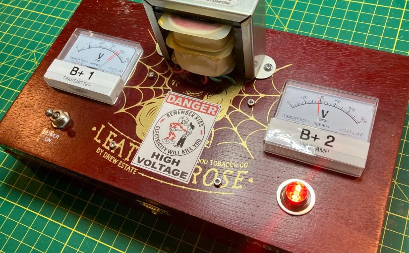
Thanks to Bob’s excellent online documentation and HamNation videos, I had no difficulty building the power supply. The only modification I made to my build, besides choosing to mount it in a cigar box rather than on a slab of pine, was that I added a neat-O vintage NOS voltage meter.

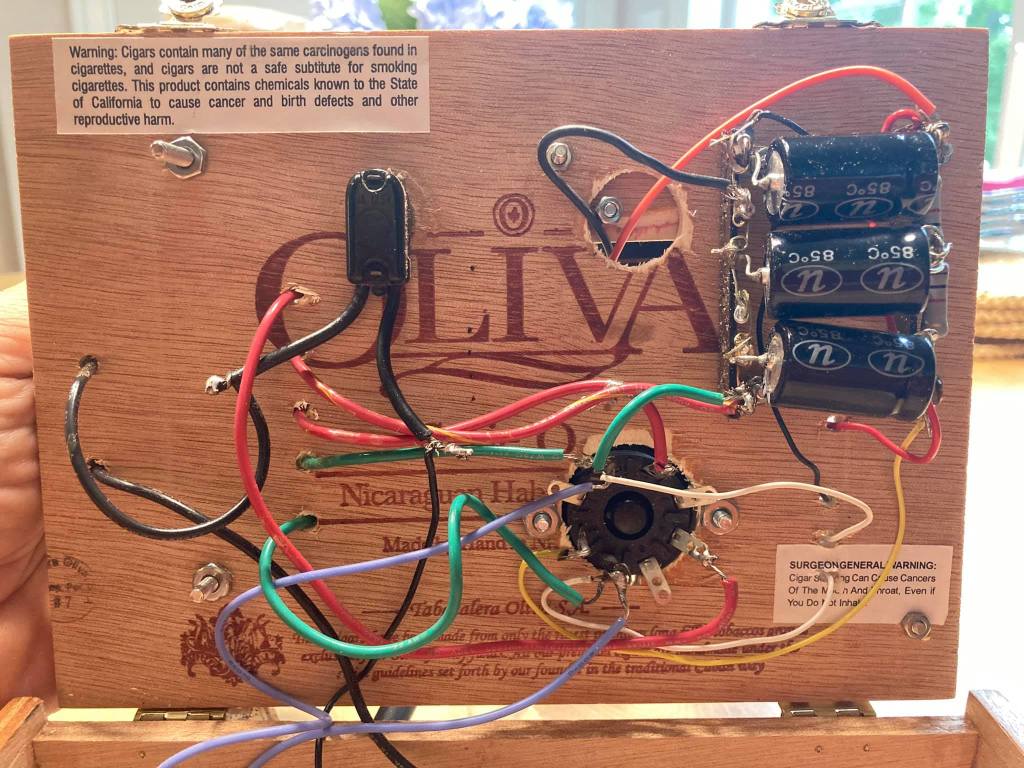
Wiring neatly hidden away on the bottom side of the cigar box lid (right.
The power supply worked great, put out about 180VDC B+, and it looked great (to me anyway!)
However, a couple of months ago, when I finally completed my build of the transmitter (watch for my future blog post), I was disappointed to record less than one watt into my dummy load on both 40 and 80 meters. I assumed I had botched something in my transmitter build and began to retrace and double check my work only to discover that all looked right.
I went back to Bob Heil’s Pine Board Project website and discovered that since he published the original plans for the power supply, which I had used, he had since uploaded modified plans replacing the 6X5 rectifier tube with a solid-state bridge rectifier. In a more recent video upload, Bob explained that changing the rectifier would result in a significant increase in B+ voltage and that it would in turn increase the transmitter RF out to the neighborhood of 5 watts.
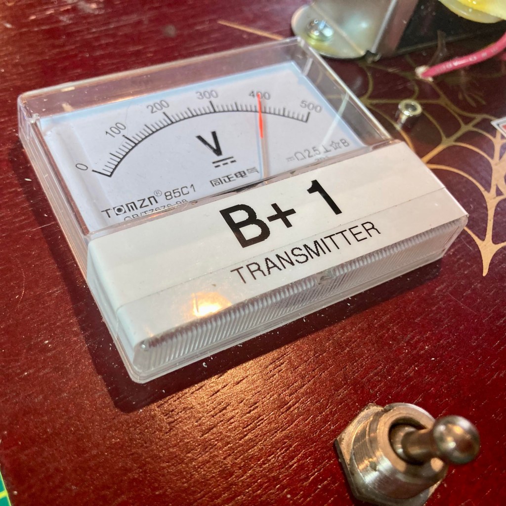
Following the updated schematic and layout plan, I modified my power supply but soldering a bridge rectifier to an octal tube base and disconnecting the center tap on the power transformer as instructed. This worked as described – my B+ voltage was now approaching 400 volts and the transmitter was putting out over 4 watts into my dummy load.
However, all was not right in the world. Upon closer inspection of the revised schematic, I saw that where there was a single B+ output originally, the capacitor/resistor network was reconfigured with two taps so a B+ of lesser than 200 VDC would be available for the 12AX7 tube in the pre-amp. According to the datasheet, the plate voltage on the 12AX7 should not exceed 300 volts.
I attempted to modify my power-supply for the second tap but ran into difficulty doing so. The version I build had included a third filter cap but the Heil redesign returned to two filter caps. I became vexed and now realized I had misunderstood the bleed resistor in my initial 3 cap build to be part of the resistor voltage drop circuit in the newly published solid-state design. Regardless of where I tried to tap the circuit for the second B+ voltage, it always equaled the near 400+ volts I was now getting on my first tap.
I decided since I had a bag full of bridge rectifiers, a drawer full of 20 MFD 450V caps in my workshop, I would salvage the transformer and begin a completely new build of the power supply this weekend working directly from the new Heil schematic.
I wanted to expand on my meter mod – since the power supply would be providing two different B+ voltages, I planned to add a second meter so I could easily confirm that B+1 for the transmitter and B+2 for the pre-amp were not the same and appropriate for their respective circuits. I purchased a pair of modern 500 volt meters since my vintage NOS meter I originally used maxed out at 300 volts.
I also decided since all of the components excepting the power transformer and meters would be mounted on the bottom side of the lid, I would abandon the terminal-strips and point-to-point wiring and instead use a perforated PCB board to make a subassembly for the filter caps and voltage drop resistors. Working rom the schematic, I designed the layout on my PC first and the built to my design.
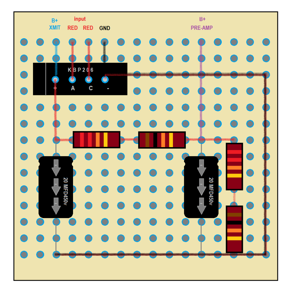

on hand, so I wired 2 22Ks in series with a 10K each to get ‘close enuff.’
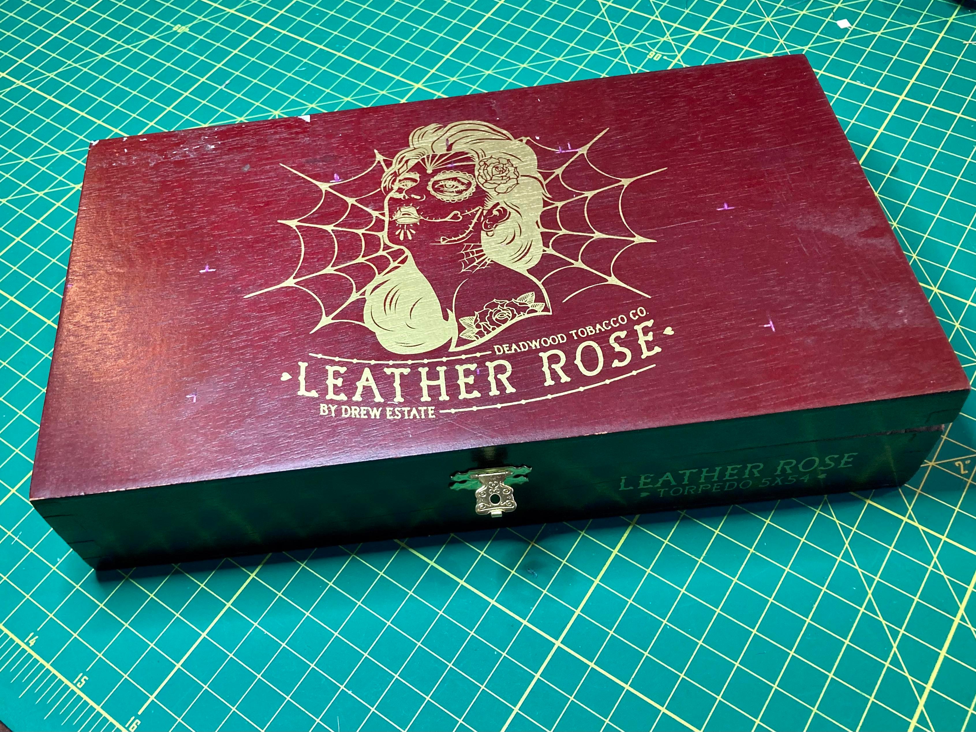
Next, I chose an appropriate cigar box from my stash for the build. Since I planned to mount the two meters to the top of the lid this time, I chose my Leather Rose cigar box as it was the widest. It was an excellent choice, I think, with one problem.
The shallow wide box was designed to hold a couple dozen cigars and the lid only needed to seal the box to protect the contents from drying out. The strain put upon the flimsy staple hinges by the heavy transformer was a bit much and I plan to replace the hinges with sturdier ‘real hinges.’
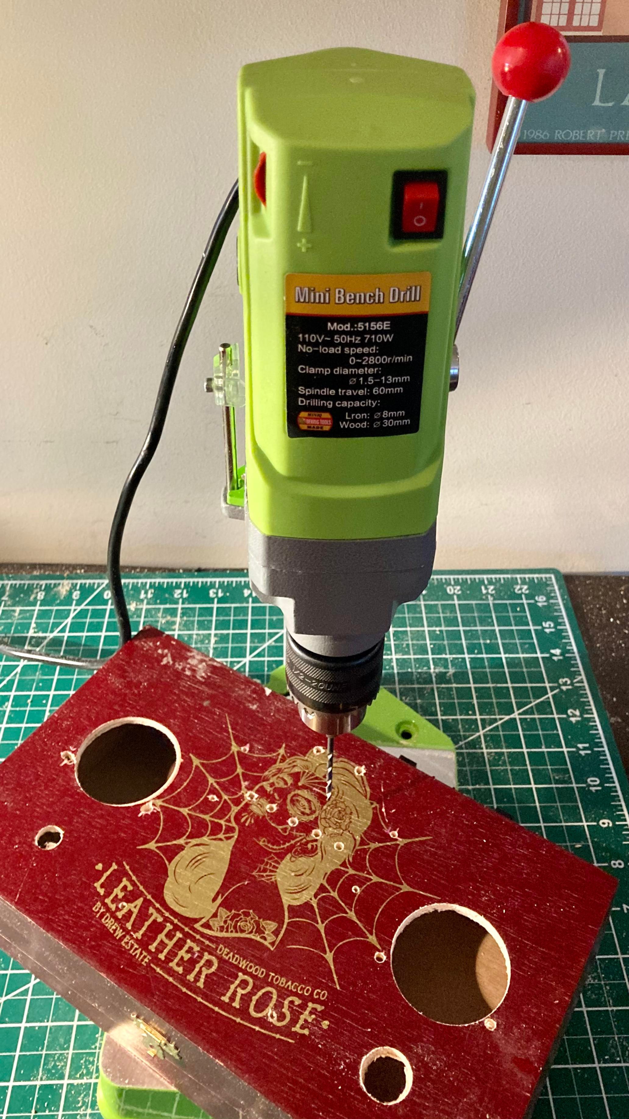
Using the new mini drill press my sister Kristen had just gifted me for Xmas, I did some precision chassis drilling in short order (right).
Once the chassis was drilled out, the rest of the assembly went smoothly and quickly. Having all of the capacitors and resistors on the PCB subassembly made for short work of all connections once the board and other chassis mounted parts were attached. Before mounting the transformer, I made all of the output connections and built a ground bus. Once the transformer was attached, it did not take long to wire up the power cord, fuse, switch and 6.3 VAC pilot light.

saved time, space and made for a neat construction.
I completed all of the work over my Saturday and Sunday morning this weekend, working slowly and carefully. My patient deliberate methods paid off as there were no snap, crackles or booms or smoke or open flames when first fired up.


Right: B+ No. 2 will provide the 12AX7 tube’s plate with a safe 190 VDC.
Finally, I want to acknowledge that this project produces lethal voltages, something we don’t deal with much anymore in this era of silicon devices. I grew up mucking around in high-voltage hollow state radio & TV chassis, and I am well aware of the proper precautions necessary for safety’s sake.
Despite the fact my regular practice is to discharge electrolytic caps and I try to be super mindful about knowing what I am touching with my hands when exploring a circuit, still I managed to shock myself a couple weeks ago while trying to diagnose why my two B+ voltages were the same after I did the first solid state mod. I was holding the power supply in my hand with the box opened, visually examining the circuitry when I accidentally touched the power out terminal strip on the top side of the box lid with my right hand.
Fortunately, despite my negligence, I did have my left hand in my pocket, a good safety practice I learned early on to prevent lethal currents from passing through the heart. That said, I encourage anyone who may be inspired by my blog and Bob Heil’s excellent plans to give this project a try – do be knowledgeable about the dangers of working with lethal voltages and how to be safe. In the end, you are solely responsible for any risks you take building or working on such circuits.

Have a comment, question, or a personal experience to share? Post a reply or please drop me a line at james@ab1dq.com.
Thanks for reading
& 73 DE AB1DQ
dit-dit
