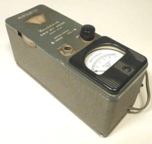
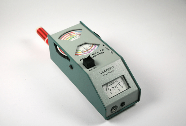
This August I picked up a pair of Heathkit HD-16 Code Practice Oscillators for $10 at the flea market at the ARRL New England HamXposition in Marlboro, Massachusetts. The CPOs were tech-specials, non-functional, but ‘mostly there’ with only a few missing parts.

BEFORE: What $10 will buy you at a ham radio flea market.
The HD-16 was Heathkit’s second code practice oscillator, introduced in 1974 and following the first Heath CPO, the CO-1 which was first sold in 1959. The HD-16 was sold until 1974, replaced by the HD-1416 in 1975 which sold with a few cosmetic variations until 1990.
Up until the turn of the century, prospective hams needed to demonstrate the ability to copy and send Morse Code at 5 words per minute (WPM) along with passing the written practical exam to earn the entry level Novice Class license. Advancing to higher class license classes required the upgrading ham to demonstrate the ability to send and receive code at faster speeds – 13 WPM for the General license and 20 WPM for the Amateur Extra Class.
In 1999 the FCC eliminated the 13 and 20 WPM upgrade exam requirements requiring hams to only demonstrate an ability to send and receive code at 5 WPM for high frequency privileges. Then, in 2006, the FCC eliminated all Morse Code testing altogether in accordance with the worldwide policy change the International Telecommunication Union made in 2003,authorizing each member country to determine whether or not to require individuals to demonstrate Morse code proficiency for licensing.
Despite the fact that hams no longer have to demonstrate the ability to copy and send Morse Code, operating CW or Continuous Wave with code remains as popular as ever in amateur radio. Many hams today choose to learn the code and many of us (yours truly included – a ham who only needed to pass a 5 WPM exam back in 2002), very much enjoy ‘pounding brass.’
Thus, the code practice oscillator, or CPO for short, was and remains a very useful piece of equipment for any ham aspiring ham to operate using Morse Code.
My Restoration Project
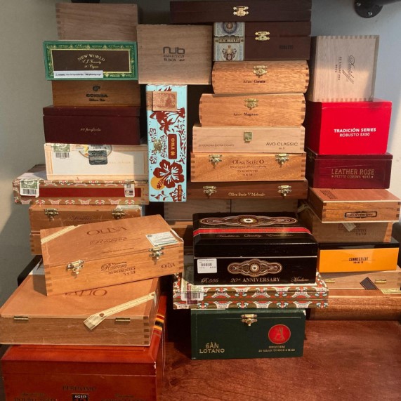
I began by disassembling both units completely and saving the screws, nuts and other hardware in (what else?) a cigar box in order not to lose any original parts.

The guts of both CPOs liberated from their cabinets.
I washed the cabinet parts in warm water and dish soap and gently scrubbed away at the stains with a soft brush. The back halves of both cabinets were scuffed and scratched badly so I chose to re-paint them in flat black.
Purists would only use the signature Heathkit dark green paint, but I didn’t have any on hand and, while I appreciate complete restorations of antiques, my philosophy for repairing old radio gear has always been to take advantage of what is available to make the vintage equipment usable to me today.
After sanding the enclosure backs with a fine grit sandpaper I applied 3 thin coats of flat black paint and then coated all pieces with 2 coats of clear coat. To compliment the blacked out cabinet sides, I also painted the speaker grilles with flat black paint and replaced the enclosure screws with new black screws.
On to the electronics
I found the original HD-16 manual online and printed a copy for reference. Like all Heathkit manuals, the HD-16’s was well written and included the schematic, complete specs, and some nice content on circuit theory and Morse Code.

Heahtkit HD-16 schematic from the original manual.
Circuit theory
From the original Heath manual…
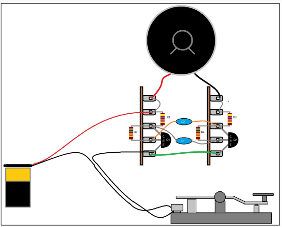
The unijunction transistor, Q1, is a special type of semi-conductor device, with two bases and one emitter, which acts as a relaxation oscillator in the following manner: When the key is closed, capacitor C2 is charged by the battery voltage through resistor R1 and the Tone control until the Emitter (E) voltage reaches the point at which the Emitter is forward biased with respect to B2.
Emitter current then flows because the dynamic resistance between the the Emitter and base one (B1) then drops to a low value. R2 drops the battery voltage to a low level, permitting C1 to charge to a higher voltage than B2.
Capacitor C1 discharges through the Emitter and Volume control until the voltage at the Emitter drops to the point where the Emitter is no longer biased. The cycle then repeats itself at a rate governed by the setting of the Tone control.
The pulsating base current, or oscillator signal, is developed across the Volume control. From the arm of the Volume control, the signal is coupled through the normally closed contacts of the phones jack to the speaker.
The lamp circuit uses the key as a switch that makes and breaks the C cell battery voltage to the lamp.
On Unijunction Transistors
When I first glanced at the HD-16 schematic, I didn’t notice that the transistor was neither a familiar BJT or a FET. Upon closer study I noticed that Q1 is a “unijunction” transistor and was labeled with two bases, B1 & B2 and an Emitter, E.
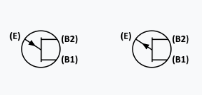
Schematic symbols for the UJT: N-type on left, P-type on right
My immediate concerns were how rare the 4JX5E670 is, and whether they or a solid equivalent can be found at a fair price today should I need to replace them. My concerns were tempered however by the excitement that this project is going to afford me the opportunity to learn something new.
Up to this point in my life, I have had a cursory knowledge of transistors. I knew the difference between NPN and PNP Bipolar Junction Transistors – their construction and function – and I had a very basic understanding of how a Field Effect Transistor differed from a BJT.
Doing a little Googling, I learned that UJTs could only function as a switch and not as an amplifier. This made sense as the ability to generate pulses would be key to function as an oscillator at the heart of the HD-16.
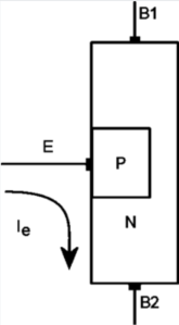
Structure of a P-type UJT (source: Wikipedia)
Back to the project… assessing the damage.
At first glance, one HD-16 was missing its lamp and the C cell battery holder. The C cell battery holder in the other HD-16 was extremely corroded. Also missing were three of the four 9 volt snaps. One of the 10K tone potentiometers was gunked up and the shaft would not turn. Otherwise, everything else appeared to be present…. not bad.
I grabbed a 10K pot from my on hand parts stock and replaced the seized control and I soaked the other pots as well as the switches with de-oxit and worked the contacts.
I decided to replace the 0.22 uF capacitors with a pair of new Mylar caps from my stock. I did not test the fixed resistors and I didn’t even bother to check to see whether I had any 4JX5E670 UJTs in my parts supply. I would dive deeper and replace any of these parts if the oscillators failed after the other work I did.
I debated whether to replace the lamps with LEDs, a popular and logical mod. Doing so meant I could eliminate the 1.5 volt batteries altogether and complete the mod by adding a dropping resistor from the 9V batteries and rewiring the SPDT switch.
I liked the way the original incandescent dial lamp looked so I didn’t do a mod for LEDs. Since I needed to replace one of the missing C cell holders and the remaining one was badly corroded, I replaced both with modern plastic holders. I attached the new holders to the inside of the cabinets using 3M 2 sided tape.
I was unable to determine whether the HD-16 was a DIY kit or was sold only as a completed unit as I couldn’t find a construction manual online. So I took the time to sketch out the schematic and trace the parts layout creating a pictorial diagram I could use to confirm the circuit was complete.

Putting it all together
I worked on both oscillators side by side, working through each step of the restorations on one unit, then the other. It made sense to work this way as I could stay focused on each step as I worked.
After completing the parts replacement I grabbed some batteries and tested each HD-16 before attempting reassembling. Fingers crossed, both worked fine and I was relieved I didn’t have to address replacing the unobtainium transistors.

One of the completed electronic restorations – ready for testing and reassembly.
Reassembly went smoothly. I started by replacing the lamp grommet and inserting the lamps into their holes on the top of the enclosures and then installing the speakers and grilles.
Next I reattached the springs on the backs of the cabinets – this was Heathkit’s clever idea to secure the 9 volt batteries securely in place – and I stuck the new C cell holders onto the back of the enclosure using 3M double sided tape.
Next I installed the switches, confirming that they were properly oriented to light the lamp when set to “LIGHT,” and then I re-inserted the two potentiometers and the key and phones jacks to the front panel.
The last thing I did before closing up the cabinet was to secure the terminal strip to one of the speaker screws. The space available was tight, but not impossible. I took special care to make sure that the transistor and other component leads weren’t shorting out against each other. I did another test of both units before closing up the cabinets.

Both HD-16 cabinets ‘re-stuffed’ and ready for buttoning up.
Finishing touches
Both HD-16s had the original metal foil serial number sticker stuck inside the cabinets, but they were in bad shape and not salvageable. So I created a “new-retro” style serial number sticker for each unit in order to preserve each CPO’s history.


AFTER: Two restored Heathkit HD-16 Code Oscillators ready for use!
Do you or did you have a Heathkit Code Practice Oscillator? If so, which model and how did you like it? Comments and questions encouraged. Drop me a line at james@ab1dq.com to join the conversation!
73 de AB1DQ
© James M. Surprenant
October 30, 2022