“Unique ham radio kits for the budget minded.” That’s what the masthead proclaims on the QRPGuys website and that is exactly what you’ll find there – a collection of project kits for the builder/QRPer that aren’t found on other kit sites and all offered at a more than fair price.
Current transceiver kits include their AFP-FSK Digital Transceiver, now in its third edition and they also offer a wide variety of other QRP essentials including several antennas and tuners, test gear including power meters, attenuators and filters and other accessories,
The QRP Guys are an affiliation of a “who’s who” of QRP building and will give you an idea of the innovative and high-quality products they develop. Ken LoCasale (WA4MNT) provides kit mechanical design, board layout and documentation, and NorCal cofounder Doug Hendricks (KI6DS) is credited with logistic support and beta testing.
Circuit design is by Steve Weber (KD1JV) of Pacific Antenna, Dan Tayloe, creator of the N7VE SWR Bridge, and Cliff Donley (K8TND). Both Steve and “Kazu” Terasaki (AG5NS) author firmware, technical assistance is given by beta builder Yin Shih (N9YS) and John Stevens (K5JS) is credited with assisting Ken with website maintenance.
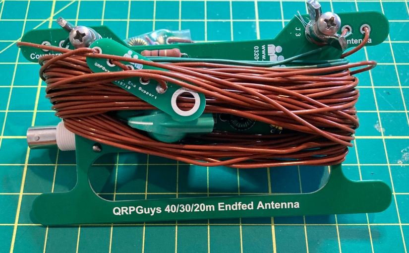
Building the QRPGuys 40-30-20 M End Fed Antenna
The QRPGuys multiband end fed antenna meets my definition of an easy build with only 16 solder-in components on the main tuner circuit board and the two traps. I started as I do with all of my kit builds by inventorying and arranging all of the parts. I have been using cigar boxes with clasps on their lids to prevent me from losing small parts before they are needed. Cigar boxes are also ideal for storing works in progress kits when a project will extend beyond a single building session.
This easy to build kit has a minimal number of parts.
The prospective builder should be forewarned that of those sixteen components, four of them are inductors that must be hand-wound on toroid coil forms. Many builders seem to abhor the winding of coils, and while I find it sometimes fiddly work, I’ve come to not mid the process.
I give props to the writers of the QRPGuys manual, as they provided some of the clearest instruction on how to wind the inductors, including the number of loops and where to place the taps. The manual also includes a nicely done illustration of each inductor and hints on how to assure the builder wound them correctly.
The diagram from the instruction manual clearly depicts how to wind the four inductors.
The inclusion of Thermaleze® brand magnet wire for the inductors was also a nice feature – the enamel coating was quickly dispatched after a few seconds of exposure to my Zippo cigar torch.
The entire build, including the winding of the four toroids, building the traps and measuring the three driven element lengths of wire took me less than 2 hours working at a leisurely pace on a winter’s Sunday morning.
BeforeAfter
About the Antenna
Field testing this antenna will have to wait a few more weeks for more reasonable weather here in Connecticut, but my plan is to use this antenna for QRP POTA activations this year with various homebuilt radios such as the Ramsey QRP20 transmitter I assembled last week. The end-fed design should make for easy deployment as a sloper while operating from the field with easy access to the tuning controls from my operating position.
The tuner circuit design is as straightforward as it gets – your basic tunable L-C circuit with a varicon capacitor. But the kit also employs the N7VE LED absorption bridge that keeps SWR to a minimum of 2:1 when set to the tune position. According to the kit documentation, the LED indicates only reflected power. Full LED brilliance will indicate an SWR at 4:1 or greater. At half brilliance SWR is approximately 2:1, and the LED will completely extinguish at 1:1.
I was impressed with the apparent high quality of the PCBs and components, and I found the instructions and supporting documentation to be exceptionally well written – easy to follow and understand.
If you would like to build the QRPGuys Multi-band End Fed Antenna, you can purchase the kit on their website here. The current price of the kit is $40 USD.
If you have built this kit, or have any questions or comments, please feel free to leave a comment or drop me a line at james@ab1dq.com.
One of the now defunct electronics kitters, whose products I personally appreciated ‘back in the day,’ was Ramsey Electronics.
Ramsey, which still exists as a firm today, but no longer sells electronic kits, produced a fairly expansive line of straight forward do it yourself solder kits that were not too complicated for the new to intermediate builder, and that came with exceptional documentation which not only provided the builder with detailed step-by-step instructions, but also included information on circuit theory explaining why and how it worked, and what the sub-circuits and individual components did. Often included were suggestions for kit mods, sometimes as provided by previous builders of the kit. Their motto was “Build It, Learn It, Achieve It, and Enjoy It!“
The Stereo FM Transmitter, a typical Ramsey kit which featured a sturdy single square printed circuit board and Ramsey’s ubiquitous four-piece plastic case. This case accommodated many of the most popular Ramsey kits and gave the finished product an easily identifiable and clean appearance.
After providing great kits to the electronics hobbyist community for more than four decades, Ramsey shut down its kit division in 2016 and has been sorely missed by hams and other electronics hobbyists ever since. Today the occasional unbuilt Ramsey kit will appear at local hamfests and on eBay, so if you’ve never had the experience of building a Ramsey kit, there’s still a bit of hope for you. For an appreciation of the breadth of their kit offerings, you can browse of one of their catalogs here.
Building a 90’s era Ramsey Kit – the QRP20 CW Transmitter
Recently, after coming across the Ramsey Active SW antenna kit I built back in the 90s, before I earned my ham ticket, but was an active shortwave listener, I found myself feeling nostalgic for the Ramsey kit experience and found an unbuilt 20 meter transmitter kit on eBay. When the auction ended four days later my bank account was $32 lighter and I found myself eagerly waiting for my new kit to arrive.
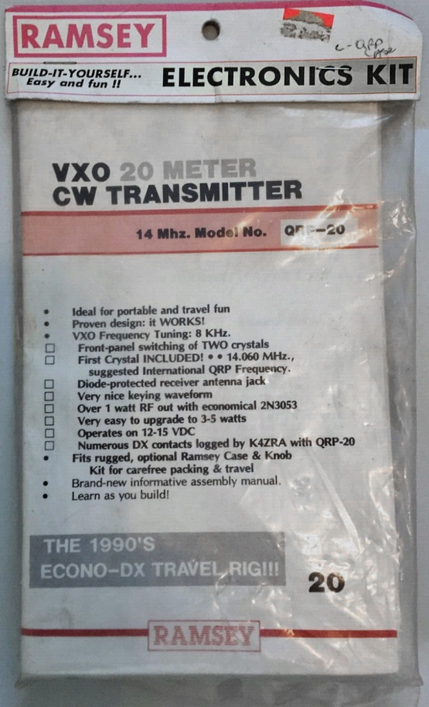
The QRP20
The kit promptly arrived a few days later, well packaged, and just as described. I was happy to see that it was unopened and complete. My winning lot included not only the QRP20 transmitter kit, but also the matching plastic case complete with pre-drilled and labeled front and back panels.
Given my recent obsession for building ham gear into cigar boxes, I planned to skip the signature Ramsey case but I realized the pre-drilled front and back panels would make an excellent template for drilling out my cigar box cabinet.
The QRP20 enjoyed favorable reviews on eHam Product Reviews with a solid four out of five stars average rating. Common among the reviews were observations that the transmitter was easy to assemble and had no drift or chirp. Several builders commented they had upgraded the cheap driver and amp Q2 and Q3 that shipped with the kit for more robust transistors for increased RF output.
The QRP20 is specified to put out 1.0 watts of RF power drawing 1/4-amp current from a 12-15 VDC source and it has two unique features to set it apart from competitors’ offerings.
The first is a space on the PCB to install a second crystal or to wire in a crystal socket. The second frequency, or socket, is selected by a pushbutton on the front panel. Ramsey included a single 14.060 crystal with the kit and leaves it to the builder to use the second crystal slot to accessorize as he desires. (I plan to add a crystal socket myself.)
The other welcome feature is the QRP20’s built in T/R switch – a nice bonus feature that will make for easy mating to the matching Ramsey HR20 DC receiver or any other QRP receiver.
Ramsey offered the QRP20 for many years and over that time, the circuit was tweaked, the instruction manual was updated, and eventually some parts were substituted for others.
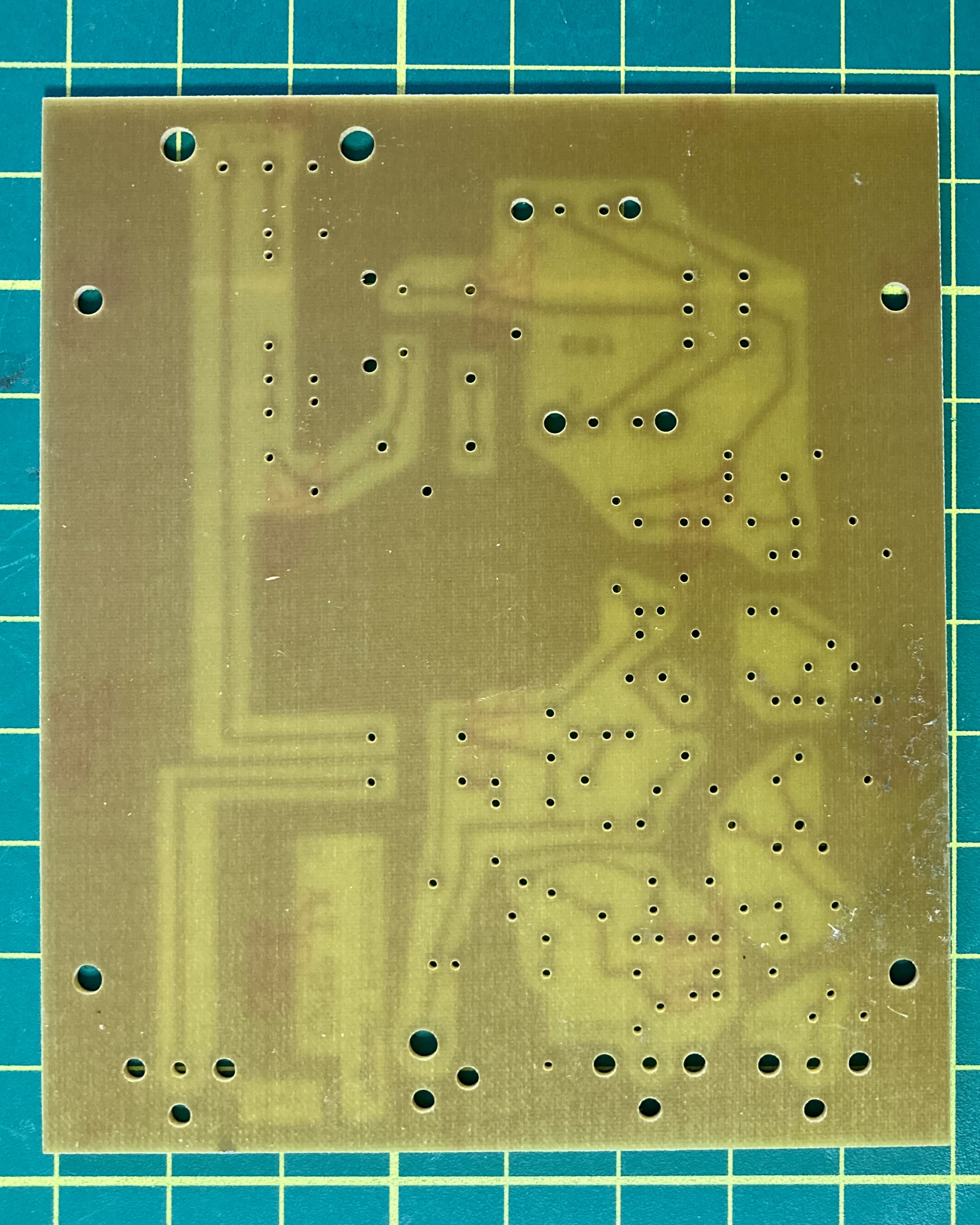
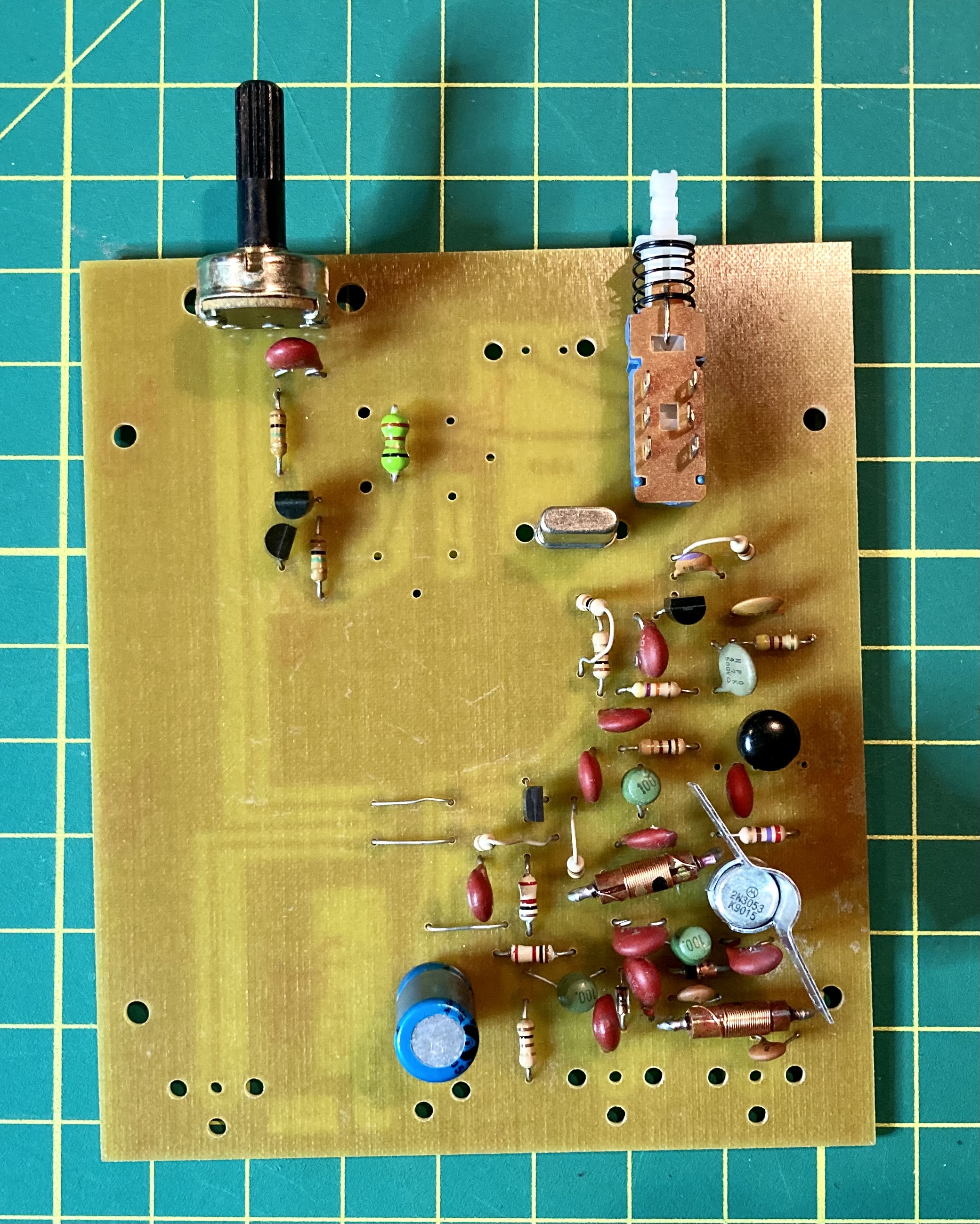
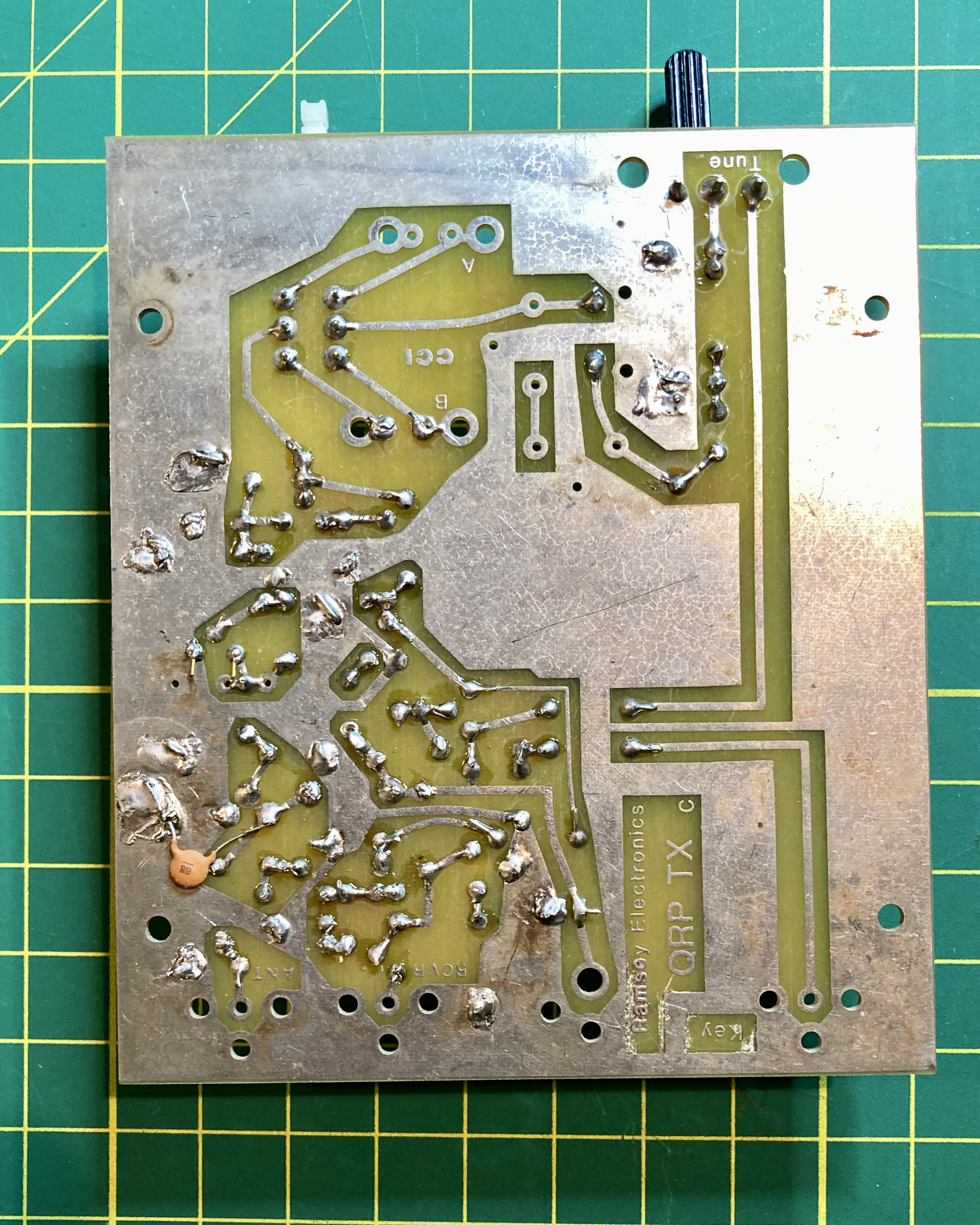
The manual in my kit was copyright 1990 and in addition to the manual, the kit included a large separate fold out parts finder diagram of the circuit board. This was most useful as this generation of the QRP20 PCB did not include screening on the component side showing individual part layout. With the Parts Finder diagram laid out on my workbench I had no difficulties identifying where every component belonged.
Assembly took about 2 hours over 3 sessions. I tend to work slowly and deliberately when kit building, and I’m a big proponent of the adage, measure 2x, cut once. In kit building, I tend to identify/measure component values thrice, solder once.
I mentioned above that over time, Ramsey modified the circuit and also some components were changed, most likely due to changing availability from suppliers. I encountered a couple of these changes in my build – all of which involved the inductors – which required a bit of extra caution on my part.
First, the Parts Finder showed a square footprint for L1, an inductor with a tuning slug. The diagram labeled it as L1 40M, with two arrows pointing to where the solder points were for the inductor. The 20-meter version of the kit that I was building, included an axial inductor with no tuning slug, the type that looks like a resistor complete with color-code bands.
The parts list stated that L1 for the QRP20 may have been either a 2.2 uH or a 3.9 uH inductor. I was able to confirm that my kit included a 2.2 uH inductor by the red-gold-red color code, and I verified the value with my L/C meter.
Inductors L2, L4, and L5 presented a bit of a challenge too. Every printed reference to these 3 inductors in the manual stated they were 220 uH and the parts list on page 20 described them as molded brown with red stripes. There was no mention in the printed instructions that the kit may have included an alternative set of inductors with different values for L2, L4 and L5. However, on the page 20 parts inventory was a parenthetical hand-written statement under the printed entry for these inductors which read “or 100uH -green 100.” There were three beehive shaped green components with a ‘100’ stamped on the top, so I felt confident these were L2, L4 and L5.
Lastly, L3 and L6 were 1.0 uH inductors but neither the instruction manual nor the parts inventory described their appearance or markings. I found two wire-wound inductors in the parts bag but they had no color code or printed markings and they were too long to easily fit in the matching holes on the PCB. But by process of elimination, I concluded these were L3 and L6 and again I confirmed their value with my L/C meter. I needed to use extra caution to carefully bend the leads 180 degress, back under the inductor body, and then 90 degrees again through the PCB holes.
The only other construction issue worthy of mentioning is the special care I took take to properly identify the leads for the four bipolar transistors. While the Parts Identifier diagram had a circular outline for each transistor with a flattened side, it did not label any of the holes as B, C and E. I connected each transistor to my transistor tester to identify the base, collector and emitter, drew a diagram in my notebook to keep the terminals straight and then cross referenced my sketch with the the schematic and Parts Layout to make sure I got these right. Having to resolder transistors after I snipped the excess leads would be a pain.
Cigar Box Considerations and Mods
I chose a nice small Nub cigar box for my QRP20 cabinet. The cigar box dimensions were 6 1/4″ x 4 7/8″ x 2 1/2″ which meant it should nicely accommodate the Ramsey 4″ x 4 3/4″ PCB. My plan was to mount the circuit board to the bottom of the cigar box and drill out holes on the front of the box to accommodate the tuning potentiometer and the crystal selector push button switch. The meant with careful drilling, I could mount both the pot and the switch direct to the PCB as Ramsey intended and have them poke through properly aligned holes in the front of the cigar box.
However, the depth of the box was a bit too long, which meant the rear connections soldered to the circuit board (antenna, receiver null, power connection and key) would not reach the back panel of the box and I would have to use chassis mounted parts for these connectors with jumpers to their connections on the PCB. I had a pair of chassis mount BNC RF connectors on hand as well as DC power barrel connector. I had a nice NOS Radio Shack momentary push-on push-off SPST button switch that I wanted to add to the back panel, so I relocated the 1/8″ jack for the key to the side panel.
Admittedly, the power switch isn’t really necessary as the transmitter is powered by an external connection to 13.8 VDC but since I added the switch, I thought it would be a nice touch to put place a miniature LED power on indicator on the front panel.
As the typical 5mm LED has a current draw of 20 mA and can handle forward voltage of 2 VDC max, I’d need to include a dropping resistor so the LED wouldn’tfry when connected to the 13.8 VDC power source.
The formula to calculate resistance is R = (Vs – Vf) / If where: Vs is Supply Voltage Vf is Forward Voltage Drop for the LED If is Forward Current Drop for the LED
Doing the math for the 13.8 VDC source: R = (13.8 – 2.0v) / 0.02 R = 590 ohms
(I padded the results a bit and grabbed a 660 1/4-watt resistor out of my stock supply.)
Final Assembly
As mentioned, the cigar box would require precise measurement. Locating the placement of the four holes on the bottom of the cigar box for mounting the PCB was easy and a good starting point.
My plan was to use 5/8″ spacers to elevate the PCB so the tuning knob would be exactly halfway between the top and the bottom of the front panel. This is where the Ramsey provided front panel came in handy as a template to get the spacing for the hole for the crystal selection push button spot on.
Since the pushbutton switch is closer to the PCB than the tunining potentiometer, I decided to place the power on LED directly above the button to give the front of the transmitter a nice symmetrical appearance.
The front and rear panels from the Ramsey custom case made an excellent template for drilling my cigar box.
Using the Ramsey rear panel piece again as a template, I was able to drill out nice venly spaced holes to mount the BNCs, power connector and power switch.
The Nub cigar box I chose for this project was a good choice not only because of its size, but also because it doesn’t have a hinged lid. The top of the smal Nub box slides on and off, which means it’s not suited for mounting radio controls to. The QRP20 transmitter with its limited operator controls made the Nub box a fine choice.
The completed QRP20 with my Lionel J38 straight key… and a can of SUPERNAUT IPA. (what a life!)
Testing and performance
Once completed, I tested my QRP20 in the shack, connecting it to a wattmeter and my dummy load. I connected my Lionel J38 straight key and powered it up with 13.8 volts DC from my Ameritron shack power supply.
Tuning my Xiegu G90 transceiver in the shack to 14.060 I was hearing my signal spot-on with the tuning knob set just past mid-point (6 on the scale of 10). I was very pleased to see I was getting just under 1.0 watts RF out…. Success!
As specified, my QRP20 produced @ 1.0 watts RF. My signal was heard precisely at 14.060 MHz with the tuning potentiometer set just beyond mid-point as shown.
What’s next?
I’d like to take this nifty 20M transmitter out into the field this summer for some QRP POTA/SOTA ops. So I will next need to consider what I will use for a matching receiver. I’ve got a few DC receiver kits I’ve previously built on hand including the most excellent TenTec 1056, a Pacific Antenna Easy Receiver, and appropriately enough, a Ramsey HR series receiver. However, all of these were built for 40 meters. I could modify one of them for 20 meters or I could build something new. Stay tuned.
Before I take this li’l rig out, I plan to complete a couple of mods. I mentioned I want to add an external crystal socket to make full use of the crystal selector button and I believe I will also try swapping out Q2 and Q3 for a bit more oomph. While I love QRP, going from 1.0 watt to 2.5 watts out could make an appreciable difference.
In conclusion
So, I had fun with this build, it brought back memories of Ramsey kit builds from years ago, and in the end I have a nice servicable 20 M QRP rig for future field ops.
What’s your story? Have you ever built a Ramsey kit? What was your experience? Do you miss Ramsey? What other kit providers today are filling the gap Ramsey left behind?
Drop me a line at james@ab1dq.com or leave a comment and let me know what you think!
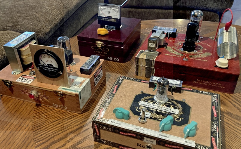
The second build in Bob Heil’s Pine Board Project is the power supply. Both the transmitter as well as the pre-amplifier feature vacuum tubes which means they require a high DC voltage for the tube plates (B voltage) as well as a lower 6.3 VAC filament voltage.
I had previously built the AES K101 battery eliminator kit for my vintage Arborphone coffin radio, which I no longer needed it for. The K101 is currently collecting dust on a workshop shelf and would have worked well with the Pine Board project. But building is fun, and Bob provided schematics and instructions for a nice simple classic tube power supply designed around the 6X5 rectifier tube.
Thanks to Bob’s excellent online documentation and HamNation videos, I had no difficulty building the power supply. The only modification I made to my build, besides choosing to mount it in a cigar box rather than on a slab of pine, was that I added a neat-O vintage NOS voltage meter.
My first build of the Heil Pine Board Power Supply w. voltage meter (left). Wiring neatly hidden away on the bottom side of the cigar box lid (right.
The power supply worked great, put out about 180VDC B+, and it looked great (to me anyway!)
However, a couple of months ago, when I finally completed my build of the transmitter (watch for my future blog post), I was disappointed to record less than one watt into my dummy load on both 40 and 80 meters. I assumed I had botched something in my transmitter build and began to retrace and double check my work only to discover that all looked right.
I went back to Bob Heil’s Pine Board Project website and discovered that since he published the original plans for the power supply, which I had used, he had since uploaded modified plans replacing the 6X5 rectifier tube with a solid-state bridge rectifier. In a more recent video upload, Bob explained that changing the rectifier would result in a significant increase in B+ voltage and that it would in turn increase the transmitter RF out to the neighborhood of 5 watts.
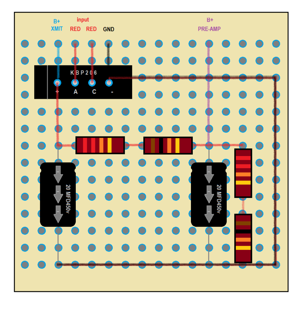
Following the updated schematic and layout plan, I modified my power supply but soldering a bridge rectifier to an octal tube base and disconnecting the center tap on the power transformer as instructed. This worked as described – my B+ voltage was now approaching 400 volts and the transmitter was putting out over 4 watts into my dummy load.
However, all was not right in the world. Upon closer inspection of the revised schematic, I saw that where there was a single B+ output originally, the capacitor/resistor network was reconfigured with two taps so a B+ of lesser than 200 VDC would be available for the 12AX7 tube in the pre-amp. According to the datasheet, the plate voltage on the 12AX7 should not exceed 300 volts.
I attempted to modify my power-supply for the second tap but ran into difficulty doing so. The version I build had included a third filter cap but the Heil redesign returned to two filter caps. I became vexed and now realized I had misunderstood the bleed resistor in my initial 3 cap build to be part of the resistor voltage drop circuit in the newly published solid-state design. Regardless of where I tried to tap the circuit for the second B+ voltage, it always equaled the near 400+ volts I was now getting on my first tap.
I decided since I had a bag full of bridge rectifiers, a drawer full of 20 MFD 450V caps in my workshop, I would salvage the transformer and begin a completely new build of the power supply this weekend working directly from the new Heil schematic.
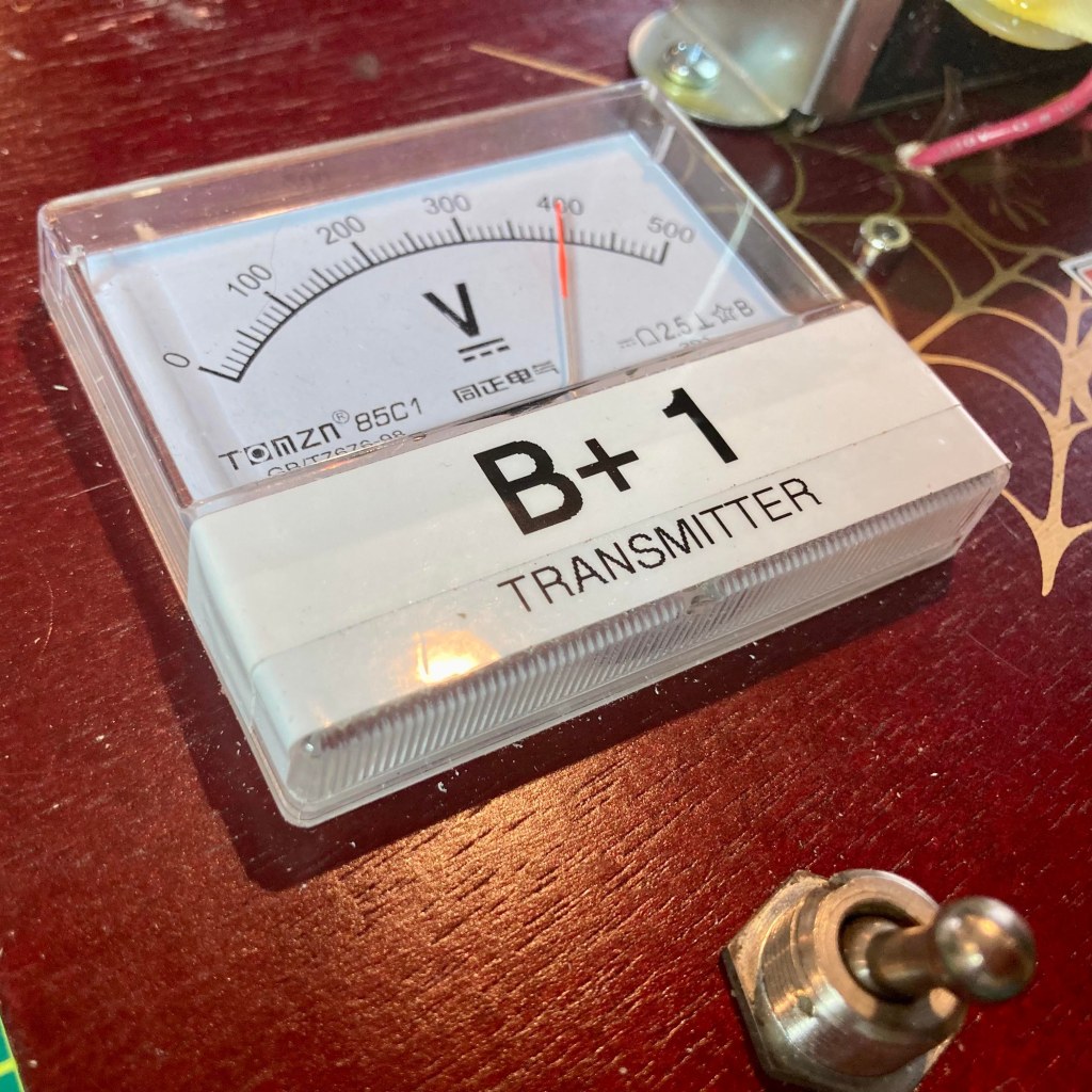
I wanted to expand on my meter mod – since the power supply would be providing two different B+ voltages, I planned to add a second meter so I could easily confirm that B+1 for the transmitter and B+2 for the pre-amp were not the same and appropriate for their respective circuits. I purchased a pair of modern 500 volt meters since my vintage NOS meter I originally used maxed out at 300 volts.
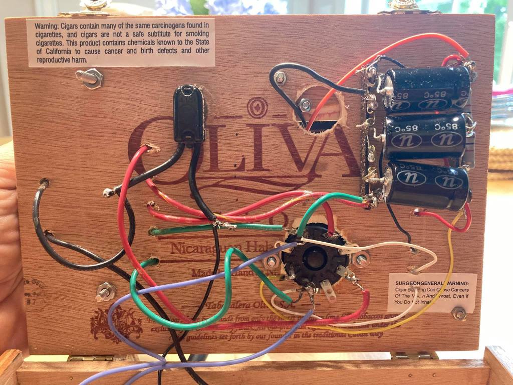
I also decided since all of the components excepting the power transformer and meters would be mounted on the bottom side of the lid, I would abandon the terminal-strips and point-to-point wiring and instead use a perforated PCB board to make a subassembly for the filter caps and voltage drop resistors. Working rom the schematic, I designed the layout on my PC first and the built to my design.
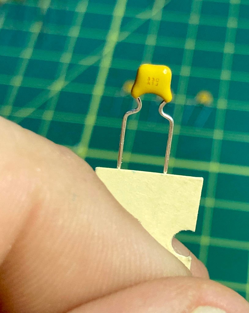
PCB layout design left, actual on right. I did not have any 33K ohm 2-watt resistors on hand, so I wired 2 22Ks in series with a 10K each to get ‘close enuff.’
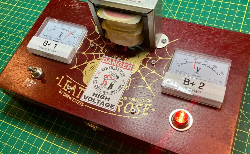
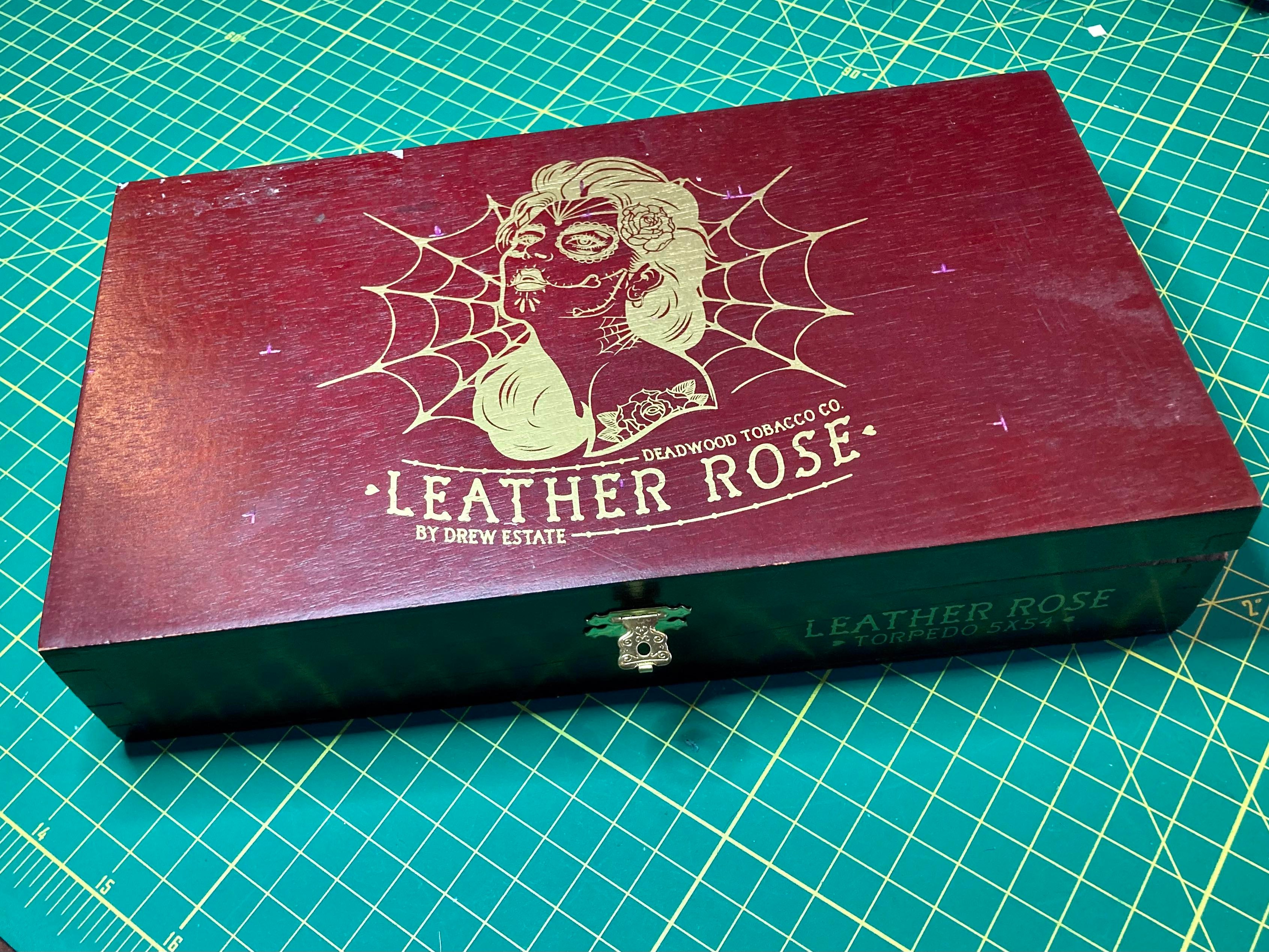
Next, I chose an appropriate cigar box from my stash for the build. Since I planned to mount the two meters to the top of the lid this time, I chose my Leather Rose cigar box as it was the widest. It was an excellent choice, I think, with one problem.
The shallow wide box was designed to hold a couple dozen cigars and the lid only needed to seal the box to protect the contents from drying out. The strain put upon the flimsy staple hinges by the heavy transformer was a bit much and I plan to replace the hinges with sturdier ‘real hinges.’
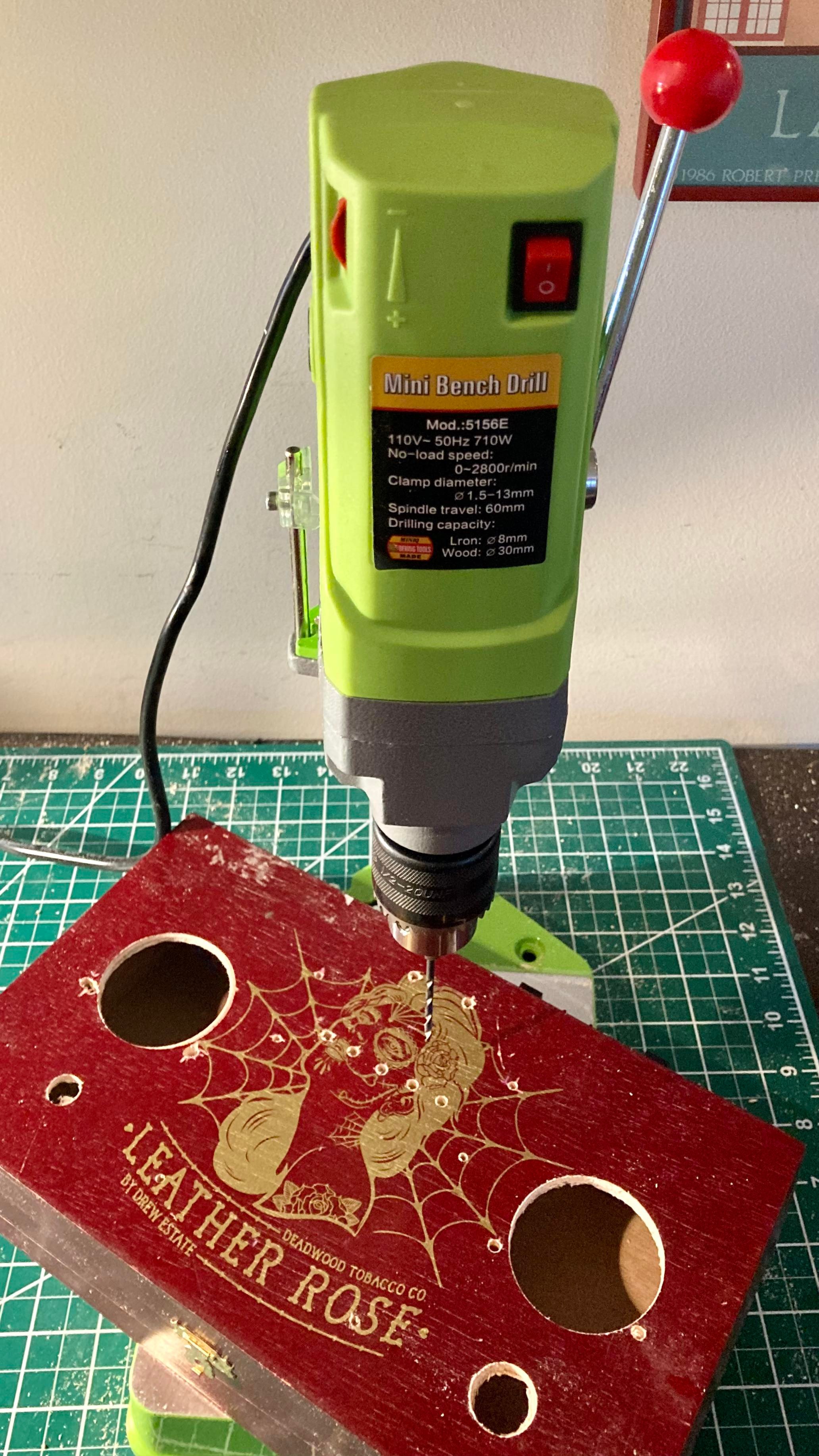
I loved the artwork on the Leather Rose cigar box (left), it was a shame to drill into it, but drill I did. Using the new mini drill press my sister Kristen had just gifted me for Xmas, I did some precision chassis drilling in short order (right).
Once the chassis was drilled out, the rest of the assembly went smoothly and quickly. Having all of the capacitors and resistors on the PCB subassembly made for short work of all connections once the board and other chassis mounted parts were attached. Before mounting the transformer, I made all of the output connections and built a ground bus. Once the transformer was attached, it did not take long to wire up the power cord, fuse, switch and 6.3 VAC pilot light.
A look under the hood, shunning point-to-point connections for the PCB subassembly saved time, space and made for a neat construction.
I completed all of the work over my Saturday and Sunday morning this weekend, working slowly and carefully. My patient deliberate methods paid off as there were no snap, crackles or booms or smoke or open flames when first fired up.
Look Ma – no smoke!Left: B+ No. 1 will be delivering nearly 400 VDC to the transmitter. Right: B+ No. 2 will provide the 12AX7 tube’s plate with a safe 190 VDC.
Finally, I want to acknowledge that this project produces lethal voltages, something we don’t deal with much anymore in this era of silicon devices. I grew up mucking around in high-voltage hollow state radio & TV chassis, and I am well aware of the proper precautions necessary for safety’s sake.
Despite the fact my regular practice is to discharge electrolytic caps and I try to be super mindful about knowing what I am touching with my hands when exploring a circuit, still I managed to shock myself a couple weeks ago while trying to diagnose why my two B+ voltages were the same after I did the first solid state mod. I was holding the power supply in my hand with the box opened, visually examining the circuitry when I accidentally touched the power out terminal strip on the top side of the box lid with my right hand.
Fortunately, despite my negligence, I did have my left hand in my pocket, a good safety practice I learned early on to prevent lethal currents from passing through the heart. That said, I encourage anyone who may be inspired by my blog and Bob Heil’s excellent plans to give this project a try – do be knowledgeable about the dangers of working with lethal voltages and how to be safe. In the end, you are solely responsible for any risks you take building or working on such circuits.
Reddy Kilowatt may seem to be a funny guy, but he does mean business!
Have a comment, question, or a personal experience to share? Post a reply or please drop me a line at james@ab1dq.com.
Legendary sound engineer Bob Heil, architect behind many signature rock artist signature sounds (The Who, The Grateful Dead, Peter Frampton, Joe Walsh to name a few), is also renowned in the amateur radio community.
Bob has engineered and his firm Heil Sound retails high performance microphones and other premium gear for the ham community, he has authored books and numerous articles for the ham community and is one of the most sought-after speakers for amateur radio conferences. Bob hosted the popular TWiT video podcast HamNation from 2011 through 2020; archived copies of the podcast remain a valuable resource to hams today.
In the Spring of 2017, Bob Heil introduced to the amateur radio community, The Pine Board Project, afour-part do-it-yourself AM transmitter project. In earlier times, building your own gear was a larger part of the ham radio experience. RF theory and design made up a larger portion the exam material and while studying, many prospective Novices would construct their own basic receivers and transmitters while studying for their licenses.
Plans for these projects were widely published – from the American Radio Relay League’s handbook and monthly magazine, QST, to other popular radio and electronics magazines such as CQ, 73, Popular Electronics, Radio TV Experimenter, and Elementary Electronics.
The Heil Pine Board project was a throw-back to these times. Bob broke the project into four separate sub-projects for the builder to construct: an RF field strength meter, a high voltage power supply, an audio pre-amplifier and equalizer, and a 40/80-meter transmitter capable of approximately 5 watts AM output.
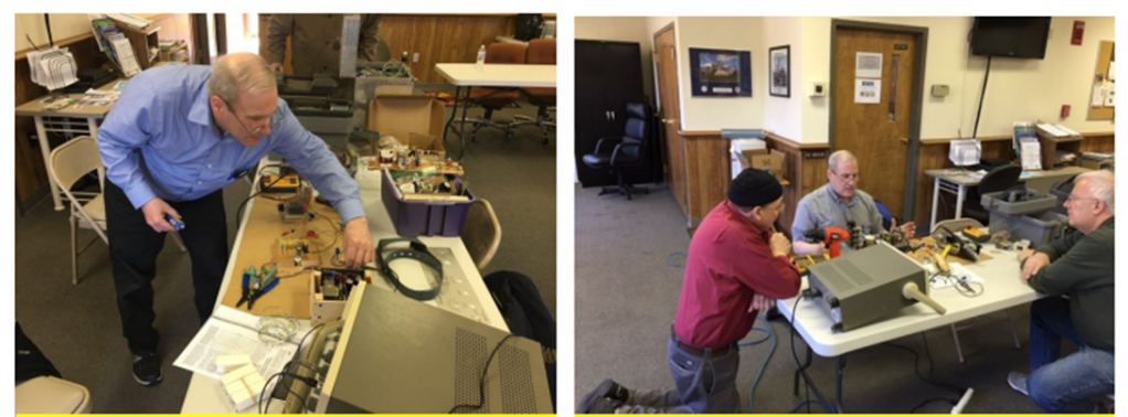
Several episodes of HamNation included featured segments in which Bob would take the prospective builder through circuit design, parts layout, and circuit theory. Bob published the schematics and board layout diagrams on the Heil website and even provided parts lists with sourcing information, giving the names of firms that carried some of the obscure parts from an earlier era, along with stock numbers and prices.
Bob’s enthusiasm for the projects as expressed in the videos was infectious. His presentation style was straight forward, detailed and inviting for the new builder. Along the way he featured photos and reports of viewers’ work.
I was hooked from the get-go. I grew up spending hours on ends in my grandfather’s TV/radio workshop in our basement and had read dozens and dozens of articles for building projects that appeared in the yellowing pages of his electronics magazines from the 60s. I had built many an electronic kit in my time, but beyond the occasional simple crystal radios or basic transistor circuits, I never did much scratch building.
I started building the projects a couple of years ago, closely following the directions and completed the field strength meter, the power supply and the pre-amplifier. Then, true to form, I either got distracted by other things (other projects, family, work, life itself).
Last summer (2021) I made a resolution to focus and complete the unfinished projects on the shelves of my workshop and decided it was time to complete the Heil project.
Friends who know me well, know that in recent years I had enjoyed the occasional cigar. Many a workweek transitioned into the weekend by enjoying a fine Leaf by Oscar and an Old-Fashioned with my dear friends Carl & Steve at the Owl. Every week or so, the Owl staff would leave empty wooden cigar boxes out at the curb for folks to take and I started nabbing a few thinking they might make good chassis for ham radio projects.
Since then I had built a few recent projects into my cigar boxes and thought that it might be fun to put my cigar box spin on Bob Heil’s transmitter project and built the transmitter into a cigar box and then rebuilt the other projects into their own cigar boxes.
At this point I’m going to blog on my Heil Pine Box/Cigar Box Project experience in a series of articles, starting with the power supply. As I mentioned I initially built this on a pine board and my initial build used the 5XT rectifier tube using Bob’s original design. I have replaced the 5XT with the solid-state rectifier, building the modified power supply as designed by and published by Bob.
Thanks again to Bob Heil for designing and sharing and promoting the Pine Board Project – it has provided me with hours and hours of enjoyment so far, and there’s much more fun ahead.
Have you built the Pine Board Project? Leave me a comment or drop me a line at james@ab1dq.com. Jump to my post about my power supply build here.
As the proverb goes, a journey of a thousand miles begins with a single step. So, after procrastinating for two plus years after my XYL and soulmate Ellen gifted me the Elecraft K2 HF Transceiver Kit for our tenth anniversary, I finally got my nerve up to start what will easily be my most ambitious kit build ever.
It is my intent to blog about my experience as I proceed, circuit board by circuit board, sharing my experience and inviting others who have built the K2 to share as well.
The Control Board
Having set up and outfitted a new protected work bench using a folding banquet table in the shack where I will work only on the K2, I started work on the first circuit board, the Control Board on January 9, 2022.
As with many kits I’ve built, the Elecraft instructions call for the builder to start by inserting and soldering all of the fixed resistors first. As others have reported, I found the instructions to be, for the most part, very well written. The instructions for the fixed resistors provided each resistor’s value in ohms as well as the color code and the builder is encouraged to install the resistors with the first color band towards the top or the right of the circuit board to facilitate verifying the correct resistor is in the correct space when reviewing or troubleshooting your work.
As electronic components have gotten increasingly smaller, my vision has gotten progressively worse as I’ve gotten older. Whenever kit building, I always verify values with my VOM before inserting any resistors into a circuit board. After installing the 13 resistors, the instructions called for the installation of seven resistor arrays and one trimmer pot, all easily identified.
The Control Board after installing all resistors.
Next the builder needs to install an 82 mH inductor, which I confirmed I had the correct part with my L/C meter, followed by a pair of silicon diodes. I then encountered the first variation in my kit. Where the original PCB had a screened space for D3, the instructions called for an 82K ohm resistor to be installed here.
The instructions next call for the builder to install and solder in place 36 fixed capacitors. Identifying and verifying the value of each capacitor was a notable challenge. Not only were the stamped or printed values on the caps miniscule, the capacitors also varied in type, shape, and manufacturer and it was clear that some of Elecraft’s suppliers changed over the twenty-five years they have been offering the K2 kit, as some of the caps did not match in appearance to the identifier pictures in the otherwise excellent parts list in the appendix.
To guarantee I placed the correct capacitor in the correct space, I took the time to identify every capacitor and laid them out neatly on my workbench in the same order the instructions called for their installation.
To identify the values, I used the camera on my iPhone and zoom in on the part. Sometimes when the value is etched on the capacitor, I needed to shift it so my bench light catches the labeling just right to read. I took the time and used my L/C meter to verify the value of every capacitor.
LEFT: using my iPhone as a digital magnifier to read capacitor labels CENTER: checking capacitor values with an L/C meter RIGHT: laying out verified capacitors in the order of installation
Once all of the capacitors were laid out in the order of installation, I carefully installed each capacitor into its space, having taken the time again to double-check values with the L/C meter. It was a slow process, but in the end, I felt very confident all of the capacitors were soldered in the correct space giving me peace of mind. Trouble shooting for mis-placed capacitors would be a very tedious process if necessary.
The next several steps went along easily as I installed the electrolytic capacitors, a trimmer cap, a dozen bipolar junction transistors, a pair of crystals, two voltage regulators, one IC socket and various connectors. All of these parts were easily identified, and when working with the transistors, I proceeded in the same manner as I did with the fixed caps, identifying and verifying value, arranging them in the order of installation and double-checking values as I installed each.
The bipolar transistors, values checked and laid out in order of installation.
Now it was time to install the ICs on the control board, and this is where I first ran into trouble.
The very first chip was an NE602, the AGC mixer. I mentioned that the K2 has been on the market for twenty-four years and over the course of a quarter century, technology moves on and the availability of parts change. By the time Elecraft had kitted my specific K2, the NE602 was no longer widely available in through-the-hole DIP casing. The industry had since begun moving on away from through-the-hole components in favor of tiny, less expensive surface-mount versions.
Instead of the DIP version of the NE602, my kit came with an equivalent SMD NE612 which was pre-soldered to a small square ‘carrier board.’ The carrier board is a PC board cut to the same footprint of an 8 pin DIP case and the builder is instructed to cut eight 1-inch pieces of wire, insert them into the eight holes on the carrier board, solder them in place, then insert the bottom ends of these wires through the DIP-spaced holes and solder to the control board.
I damaged the carrier board while attaching the wires by working sloppily with a too-hot iron. The carrier board was not of the same high quality as the control board which featured double plated holes. The carrier board had plating only on the top of the holes, and I managed to lift the plating off of the number 2 and number 3 hole, breaking connectivity. I tried to bridge the contacts to the chip contacts with a solder blob, but that only made a bigger mess of things.
LEFT: the Control Board space for U1, an NE602 DIP RIGHT: The SMD carrier board for U1 which I damaged with a heavy hand and hot iron
Elecraft has a form on their website to order replacement parts and I reached out on January 1qth to inquire about purchasing a replacement NE612 and carrier board. I did receive an acknowledgement that they received my inquiry from a mail bot, but as of this writing, four days later I have not received an actual reply.
In the meantime, I began wondering whether I could still find DIP cased versions of the NE602 elsewhere online. I searched Mouser, Digi-key, eBay and Amazon and found that an Amazon vendor had some available, which I ordered. The vendor did not disclose the name of the manufacturer nor the source country, but I’m assuming the chips were manufactured in China. I did order five (there are three others elsewhere in the K2) and they arrived within a day or two.
I discussed my dilemma with one of my Elmers, Steve, KZ1S, who has built many a kit in his day and is a physics professor who works with electronic circuits and RF in his work.
Steve offered a couple of suggestions. The first was to use a proper SMD to DIP converter board with proper pins spaced correctly. I liked this idea very much, but the drawback is that it would require me soldering the SMD chip to the converter board and again, with my failing vision and dexterity, this would be a bit of an unpleasant challenge.
A proper SMD – DIP converter
Steve also suggested looking for genuine NOS chips online, either on eBay, or from Radwell International. Steve mentioned you can source just about any obsolete part with Radwell, but they can be expensive. I did locate the NE602s on there with a retail price of about $5 – not a deal-breaker, but given I need four for the K2, that’s an additional $20 + shipping.
For the time being, I decided to place a DIP socket on the control board and once in place, I inserted the NE602 of dubious origin I purchased from Amazon in the socket. For the time being this would let me continue with the build and be able to test resistances. I could then swap out the AGC chip for a genuine NOS or SMD + converter at a later date.
I finished the build of the control board this morning, directly soldering in the remaining ICs and adding the two CW key-shaping capacitors on the solder side of the board.
After carefully double-checking all of my work, I used my VOM to perform the resistance checks. All of my test resistances were within range, excepting U6 pin 29 (DASH) and U6 pin 30 (DOT/PTT) which were marginally over spec. The acceptable range for both is 70K – 90K ohms and I measured 96.6K on pin 29 and 96.8K on pin 30. I will revisit these values later.
So that concludes the build of the first circuit board, the Control Board. I counted a total of 110 components soldered to the board and I completed the work in eight days working at my deliberately leisurely pace.
I welcome comments and suggestions from any and all, particularly from anyone who has built the K2 and had to deal with the SMD carrier board themselves. Drop me a line at james@ab1dq.com to share your thoughts and opinions.
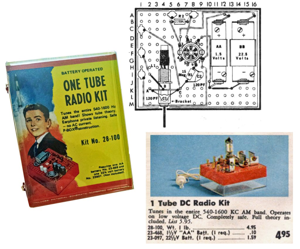
I built my first electronic DIY kit when I was about 10 years old. Dad brought home the Radio Shack One-Tube AM receiver P-Box kit and we spent the better half of the following Saturday at the workbench in the basement building it together.
It was an amazing formative experience – spending the day working on the project with dad, learning about the various electronic components and how they worked in the circuit, and getting my first try at soldering.
I treasured the completed radio and can vividly recall that magic moment when I first clipped the ground wire to an exposed gas pipe behind the parlor stove, sticking the hard plastic crystal earpiece in my ear and tuning the loopstick and hearing WBZ in Boston coming in loud and clear on the radio dad and I built out of a handful of parts.
This was the first of many Scie`nce Fair™ P-Box kits I would build throughout my early teen years. No Christmas or birthday was complete without one (or two!) new kits. I remember building the organ, the two-transistor AM radio, the “GoofyLight,” the indoor/outdoor electronic thermometer, the moisture detector, the AM Wireless microphone and the frequency standard.
My first kit build – the Science Fair ONE TUBE RADIO KIT, sold by Radio Shack circa 1974
I was hooked on kit-building and at some point, in my teen years I saw my first Heathkit catalog and was blown away at the more complex scale and wide variety of Heathkits… radios, hi-fi gear, test equipment, computers, even television sets. I began setting my sights on taking my kit-building to the next level.
However, in the mid- to late- eighties my focus and all of my earnings went into getting through college. By the time I had the time and disposable income to return to the kit-building workbench, the Heathkit era was sadly over.
At the turn of the century, I was in the position to have the time and money to return to my radio and electronics hobby. In 2002 I earned my amateur radio license and from the get-go started building ham-radio related kits. These included receivers and QRP transmitters and a variety of accessories like tuners, station clocks, sold by kitters such as Oak Hills Research, Four State QRP Group, MFJ, Small Wonders Lab, TenTec, and Rex Harper (QRPMe), among others. These were fun builds and there is nothing like using gear you built to make contacts on the air.
However, even the best ham gear I built still fell short of having built and having a showpiece full feature 100-watt multi-mode transceiver like the venerable HW101 in my shack.
The Heathkit HW101 `100-watt 10-80 m transceiver
In 1998, Elecraft, a new retailer of amateur radio gear was founded in California by Wayne Burdick and Eric Swartz with the introduction of their first product, the K2, an HF transceiver that could be purchased as a kit or fully assembled.
The K2 features dual VFOs with multiple memories, split TX/RX operation, RIT/XIT, full break-in CW, memory keyer, narrow IF crystal filtering, and IF derived AGC and the base radio can be built as a 5-watt QRP CW rig with optional accessory boards available to add SSB and amplify the RF output to a full 100 watts.
Initial reviews by the ARRL and other professional publications as well as those written by amateurs who have built and operated the K2 were excellent. The consensus was that the K2 has become a worthy choice for builders lamenting the disappearance of Heathkit. Reviews cited that the Elecraft kits were well packaged, completed, and the instruction manuals and documentation provided was detailed and easy to follow – not unlike the Heathkit manuals of a prior generation. Elecraft also got high points in published reviews for excellent customer support.
A bit over two years ago, my wife Ellen gave me the K2 kit, along with the 100 watt amplifier board and the SSB board as a gift for our tenth wedding anniversary. (I frequently point out that no man ever married better than I!)
Although I wanted to build the K2, and indeed put it on my gift ‘wish list’ – I let it sit in the workshop for over two years! I knew the project would take months on end to complete, and in order to succeed I would need to maintain a clean workspace, take my time and work slowly and diligently.
I think I have many fine qualities, but I’d be the first to tell you attention to detail and neatness are not among them. I was further intimidated by the fact that electronic components have gotten smaller while I have gotten older. My vision, which was always poor from birth, wasn’t getting better and my hands are starting to get a little shaky.
I finally resolved as we headed towards 2022 to tackle the K2. I created a new ‘protected’ workspace in my shack/mancave, moving in a folding banquet table, topping it with a pair of self-healing cutting mats and setting up my magnifier lens, solder station, some essential hand tools and my VOM, capacitance/inductance meter and my laptop.
The bigger resolution was to keep this space protected and clean. I resolved to not let this space become cluttered. I would not place anything not Elecraft related on this dedicated workspace, and I also resolved to clean up the space every time I stopped work, making sure I didn’t leave any loose parts out.
HIYA SMOOOOOOOOOSHIE! Cats don’t understand ‘protected workspace‘ nor do they care that much.
And with all that in mind, I finally started my build this month and my intent is to blog about the experience here and intend to blog as I complete each board. I invite you to join me for the journey. I hope those who have already built the K2 reach out with comments, tips and tricks – any input will be most appreciated. I also hope that this blog may be a resource or an inspiration for other builders.
Please feel free to leave a comment or write to me at james@ab1dq.com.
As I write this in May 2021 there is much excitement in the amateur radio community as Solar Cycle 25 has been confirmed to have finally begun.
Every 11 years or so, the Sun’s magnetic field completely flips. This means that the Sun’s north and south poles switch places. Then it takes about another 11 years for the Sun’s north and south poles to flip back again.
The solar cycle affects activity on the surface of the Sun, such as sunspots and solar flares which are caused by the Sun’s magnetic fields. As the magnetic fields change, so does the amount of solar activity on the Sun’s surface which produce large emissions of radiations from the surface of the sun into space.
For amateur radio operators high solar activity means more favorable conditions for operating DX, or making long distance contacts. Radio waves, which are electro-magnetic can be reflected off of highly ionized layers of the earth’s atmosphere. The more ionization in the atmosphere, the better the operating conditions. When solar flares release radiation into space, that radiation will increase the ionization of the atmospheric layers where radio waves are reflected.
Thus operation conditions and the opportunity for DX contacts on the HF bands is expected to continue to improve as we head towards the anticipated peak of Solar Cycle 25, which should occur in 2025. This is great news for holders of General and Amateur Extra Class licenses as they both have broad privileges to the HF bands that will benefit from the increased solar activity.
The majority of amateur radio operators holding the entry level Technician Class license typically enjoy their on air time, operating inexpensive handheld transceivers to make contacts via local FM and DMR repeaters. Many Techs may enjoy the thrill of making “DX” contacts working other hams around the world via VOIP platforms like IRLP and Echolink which are accessible with their VHF/UHF privileges, but few take advantage of the opportunity to work “real RF DX” on the 10 meter band where they have limited HF phone privileges from 28.3 – 28.5 Mhz.
This is understandable, assembling an HF amateur radio station can be a daunting undertaking, and expensive. A new entry level multi-band transceivers such as the Icom IC-718 costs $600, and you can spent thousands more for more feature packed rigs.
Then there is the matter of choosing and raising an antenna for HF. This can be daunting as there are many varieties of antenna designs and there are many variables to consider.
Assembling a full featured HF station can be costly, complicated, and given that Technicians can only operate on the 10 meter band, doing so is a bit of overkill, at least until they upgrade.
This article provides information for the Technician licensee who would like to get on board to work DX on the 10 meter band as solar conditions improve. I will provide a technical primer on the 10 meter band and then thoughts, ideas and instructions on how to assemble a 10 meter only station, which not only easy and fun, it can be done for a fraction of the cost of building a multi-band HF station.
About the 10 Meter Band
The 10 Meter band is a low noise daytime band ranging from 28.000 – 29.700 MHz is at the very top of the HF frequency range. Here is the band plan for 10 meters:
If you would like to learn more about the 10-meter amateur radio band, may I recommend this excellent video by the Official SWL Channel on YouTube.
10 Meter Propagation
At peak times of the solar cycle, 10 meters will be alive with DX, refracting from the F2 layer in the ionosphere. The best propagation of 10-meter radio waves occurs during local daylight hours, but it is not unusual for the band to be open before sunrise and continue into the night when there are high sunspot activity.
The F2 layer forms during daytime hours between 200 km and 400 km above the earth. It is usually around all year around, and is at a higher altitude during summer months than in the winter. At night, the F2 layer will merge with the F1 layer to form a single F layer, which will be a bit lower in altitude than the F2 layer was during the day. Although the F2 layer exists all year long, it may sometimes disappear completely for days during a deep solar cycle minimum
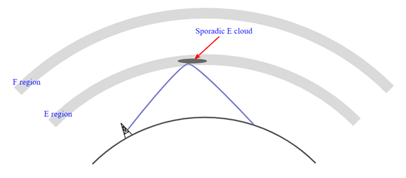
In times of solar minimum, long distance contacts are still possible on 10 meters as Sporadic E propagation can bring in signals from a hundred to many thousands of miles away. Sporadic E is primarily seasonal with late spring and early summer being prime time for the mode.
Sporadic E arises when very intense clouds of ionization build in the lower reaches of the E region of the ionosphere. Sometimes these dense ionized clouds form suddenly and disappear just as suddenly minutes later. Sporadic E occurs most often in the months of June & July and December in evening, but it can happen at anytime. During a Sporadic E incident, ionization may be up to five times greater than those normally achieved at the peak of the sunspot cycle.
The 10 meter band is the only HF band that is affected by Sporadic E propagation, is typically benefits the VHF range including 6 and 2 meters, but typically won’t affect frequencies below 28 MHz.
Assembling your fixed 10-meter station – Choosing a transceiver
The most essential piece of an amateur radio station is of course, the transceiver. Even with the mythological perfect antenna, you need a receiver to hear other stations and a transmitter to put your signal out.
Most commercial amateur radio transceivers today are multi-band, that is, they can operate on most or all of the MF and HF ham bands, and several will also have functionality for all mode VHF and UHF operations. You can spend anywhere from about $500 to several thousands of dollars for a state of the art HF transceiver, and this may make the prospect of setting up a station to work 10 M phone only a non-starter for the Technician.
Fortunately, there are more reasonably priced alternatives available in terms of new and used 10 meter only radios. A careful shopper can expect to pay anywhere from under $150 to $500 for a used or new radio.
My recommendations – used 10 Meter Rigs from the 1990s
I recommend the Technician looking to get on 10 meters first consider purchasing a used 10-meter only radio that is in good operating condition. In the 1980s through the early 2000s, Radio Shack, President and Ranger marketed 10 meter radios that have SSB phone functionality. If not abused and relatively well cared for, these radios will be an excellent choice for the 10 meter Technician.
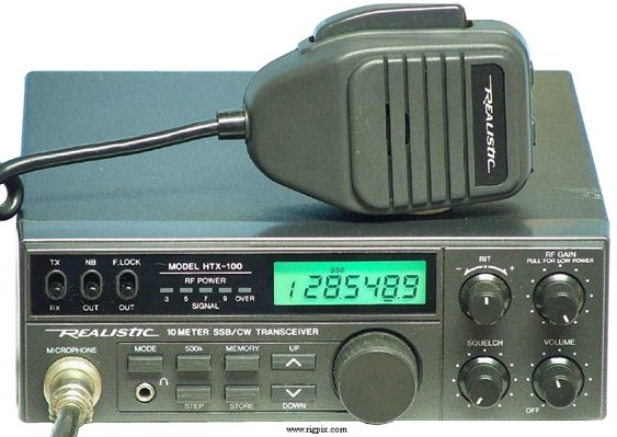
Among these radios, I recommend the Realistic HTX-100, also marketed as the President HR2510, from 1988 into the 90s. The radio was manufactured by Uniden and featured 25 watts PEP output on CW and SSB. This radio lacks FM functionality, so you could not use it for 10 meter repeater operations. Today they can be found in working condition in the $100 – $200 range at hamfests, on QRZ.com and on eBay.
When shopping for an HTX-100 or HR2510, do be careful. Carefully examine the radio or seller photos and inquire not only whether the radio is fully functional, but find out if the radio had been modified. These radios were popular for mods, particularly for out-of-band transmitting. Ideally you want to find one that hasn’t been modified.
Watch for obvious signs of modifications, damage or abuse/neglect. Several of these radios today suffer from black marks on the LCD screen. As long as the frequency and other information on the display aren’t obscured by the black marks, the problem is only cosmetic and won’t affect the radio’s useability. Do watch for units that have no display functionality at all.
Another problem with these used radios is sometimes the frequency can’t be changed via the rotary encoder tuning knob. Radios in this condition can usually still be tuned via the up-down frequency buttons. If you decide on a radio with this malfunction, make sure the price you pay reflects this.
The Realistic HTX10 (President HR2510) can be an exceptional 10M only rig.
The President HR2600 was a follow up more upscale revision of the HR2510, also made by Uniden, but this time not available from Radio Shack as a Realistic variant. In addition to SSB and CW, the HR2600 was capable of AM and FM operation, and even included a CTCSS tone board for repeater operations.
Like the HR2510, the HR2600 had a power output of 25 watts PEP for CW and SSB, and could put out 10 watts on AM or FM. The same caveats as listed above for the HR2510 apply for shoppers looking for the HR2600. This radio can also be found in the $100 – $200 price range used today.
The President HR2600 is a quality all mode 10M transceiver.
In the late 90s and early 2000s, Radio Shack marketed another 10 meter only mobile rig, the HTX-10. The HTX-10 was manufactured by Maycom. The chassis of the HTX-10 was considerably smaller than the HTX-100, more in line with mobile 2 meter FM or CB transceivers of this era. The HTX-10 did not have CW functionality, but did have AM, FM and SSB phone modes. The transmitter put out 7 watts PEP on AM, and 25 watts on SSB.
The HTX10 can be found on eBay and QRZ to this day and you can expect to pay anywhere from $100 – $150 for a unit in good operating condition.
The Radio Shack HTX-10 did not have CW functionality, but was more in line with mobile FM VHF and CB transceivers of its era.
Modern Options, aka “Export Radios”
Today most of the new radios sold as “10 Meter” radios are in fact not so much as intended for amateur radio operators, but for people to modify and operate illegal power in the CB band, or 11 Meter Range.
By law, CB radio operators are limited to 4 watts PEP in AM mode and 7 watts PEP when operating SSB. In 1982, President Regan signed into law a bill that allowed the FCC to stop issuing individual CB licenses and to scale back enforcement of operating rules on the citizen’s band.
Although the law eliminated the need for individual licenses, the FCC never changed the rules or regulations for use of CB radio. To this day it remains illegal to operate a CB radio with more than 4 watts PEP on AM or 7 watts on SSB.
Despite this, many folks today run illegal power in the 11 meter band and do so outside the pre-defined channel frequencies. They do this by either adding an amplifier to an existing CB radio, modifying a pure CB radio to put out more power, or converting a 10 meter amateur radio transceiver for use on the 11 meter band.
Several manufacturers today sell what are known as “export radios” – these are CB radios that can not be legally sold in most countries. Either the power output is too high, the frequency range is too wide, or some modes aren’t allowed. Some manufacturers use is to initially limit the frequency range to 28.000 – 29.700 MHz and advertise these radios as ham radio transceivers making them legal to sell to the amateur community. The majority of customers who purchase these radios are not amateur operators but radio scofflaws who will modify them into an (illegal) CB radio.
The catch for you, however is that these are actually what they claim – 10 meter amateur transceivers and they can be used to operate on 10 meters. Several are inexpensive and some are lacking in quality. Here are a few worth considering.
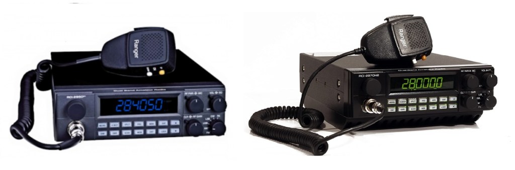
Ranger Communications is a CB and amateur radio manufacturer based in Taiwan with a USA division. Their radios have been manufactured overseas in plants in Vietnam, Malacca, Malaysia, Shanghai and Taiwan.
For years Ranger has sold a series of 10 and 12 meter radios for several years all featuring a similar form factor. This line of radios includes the RCI-2950 and RCI-2970 radios and in addition to being available used, new radios are still being produced with various features and identified by the model number suffix.
The Ranger RCI- 2950CD is a 10/12 meter transceiver that puts out 25 watts PEP on SSB and 8 watts on FM/AM and CW. The radio has a current MSRP of $290 new.
The Ranger RCI-2970N2 DX is a 10/12 meter transceiver that is capable of putting out a whopping 200 watts PEP on SSB and 100 watts on FM/AM and CW. It has an MSRP of $450 new.
A pair of Rangers: The RCI-2950CD (left) and the RCI-2970N2 DX (right)
In Feburay 1992 QST published a side-by-side comparison of the Ranger vs. the HTX100. In conclusion, the HTX came out ahead overall, and the ARRL was “generally disappointed with the RCI-2950. If you have any doubt who the Ranger line are marketed for, consider the fact that these radios have CB features such as the “roger beep” and PA, and adding ‘talk-back’ is a very popular mod.
Anytone, known today primarily for their DMR handheld and mobile radios, also offers a pair of 10 meter mobile radios. The current iteration is the AT-6666 and can be had from Amazon.com for $266 at the time of this writing. It puts out a hefty 60 watts PEP on AM and SSB, and 50 watts on FM.
The previous version, still available new is the AT-5555N. It puts out 30 watts PEP on SSB and FM, 12 watts on AM. Currently it can be found on Amazon for $230. I have not read or seen any reviews of these radios, but if you have used either, please feel free to drop me an email at james@ab1dq.com.
The Anytone AT-5555N (left) and the AT6666 (right)
The Antenna
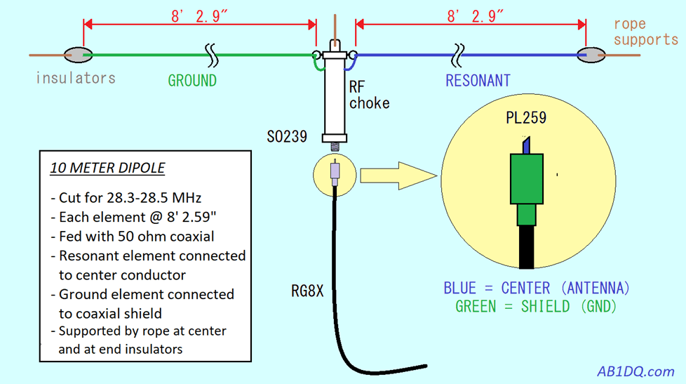
Of course you will need a resonant antenna in order to put your signal out on 10 meters, and the easiest and most inexpensive way to do this is to construct a classic half wave wire dipole antenna. Building your own 10 meter dipole is simple, easy, affordable and fun.
The dipole is a straight electrical conductor consisting of two equal lengths of #12 or #14 stranded wire with a combined length measuring 1/2 wavelength from end to end. It is supported with rope or nylon cored from the center and each end and connected at the center to a radio-frequency (RF) feed line that is then connected to your transceiver.
A half wave dipole cut and tuned for the center frequency of 28.400mhz should cover all of the Technician 200khz spread with low SWR and will allow you to work the entire sub-band without the need of a tuner.
The basic design and dimensions of a 10 Meter Dipole antenna for the Technician sub-band.
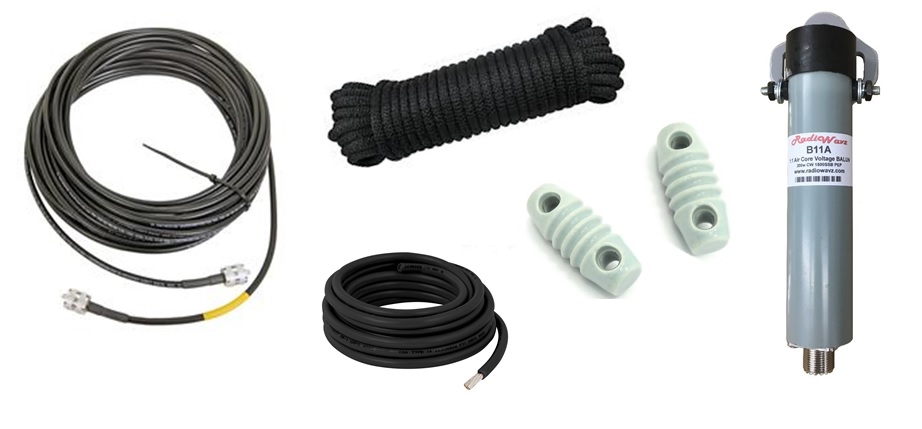
Here is a list of all materials you will need for your dipole:
20’ of 12- or 14-gauge copper stranded wire
Coaxial feedline – RG8X is sufficient and light
Connectors and insulators
Rope
1:1 Balun (RF Choke), optional
The essential ingredients for your 10-Meter dipole from left to right: RG8X coaxial feedline, insulated stranded copper wire, nylon rope, insulators, and an RF choke (or center insulator)
The insulators can be homebrewed from any non-conductive material (glass, plexiglass, PVC, wood, commercial made insulators, etc. The center insulator actually can be used both for support at the center and to prevent the two outer radiators from touching and needs to be able to handle the weight of the entire antenna, coax and support ropes. if you incorporate the RF choke, that will do double duty as your center insulator.
A brief aside… Balun or no Balun?
Many recommend incorporating an RF choke or a 1:1 current ‘balun’ at the point of where the feedline meets the antenna elements. The word balun is an amalgamation of the words balanced and unbalanced and it provides common-mode isolation between the antenna and feedline. In our model, we only need it as an RF choke and serves the purpose preventing stray RF from coming back down the shield of the coax and into the shack.
My recommendation is that you may wish to initially construct your antenna system without the choke, and later modify the antenna if you experience a problem with stray RF. You will know you have a problem with stray RF if you experience RF burns, or you note RF interference with other electronic devices such as PCs, televisions, digital clocks while transmitting.
There are many 1:1 baluns available commercially from reputable manufacturers and retailers such as DX Engineering, Jetstream, MFJ, Quicksilver Radio and Radiowavz. A good rule of thumb in buying a balun is you can expect to get what you pay for – expect to pay $30 – $100 for a good balun and maybe avoid AliExpress, BangGood, and eBay. Expect to pay $30-$100 for a quality commercial current balun
You may also wish to construct what is known as an ‘ugly balun’ – which is easily constructed with a 25 feet of spare coaxial cable and should be effective eliminating stray RF issues. There are numerous resources for this on the web if you’re interested. Start with this HamUniverse article and/or watch Jim Haslett’s “How To” video here.
Choosing your feedline
Just as you need to make compromises when choosing an antenna, design, you need to select the best balance of different factors for your installation when choosing a coaxial feedline. These include:
Weight
Loss
Flexibility
Cost
For the 10 meter dipole, weight is your primary concern, followed by line loss and cost. Heavier feedlines add more strain to the antenna connections and support rope so a lightweight feedline is preferred. Regarding line loss, while higher frequencies mean higher line loss, at 28.3 – 28.5 MHz, still in the HF range, loss won’t be as significant of a factor as when feeding a VHF, UHF or higher band antenna.
RG8X provides a nice compromise of weight, loss and is particularly inexpensive. Calculated loss for a 50′ run of RG8X at 28.4 MHz with a load SWR of 1.5, is 17.84%. If you’re putting in 25 watts PEP under these circumstances, calculated power out is 21.89 watts; not bad at all. At the time of this writing, a 50′ run with SO239 connectors retails for less than $40 at QuickSilver Radio.
Tuning Up
The last thing you will need to do before going on the air is to tune your half wave dipole antenna. The process is simple and straight forward.
The dipole antenna is to be tuned for the lowest SWR across the portion of the band you will be using it for. For our purposes, we want the lowest SWR for the Technician phone portion of the 10 meter band, which is 28.300 – 28.500 MHz. Tuning for lowest SWR at 28.400, the mid point of the Technician phone sub-band will allow the antenna to perform well across the entire Technician sub-band.
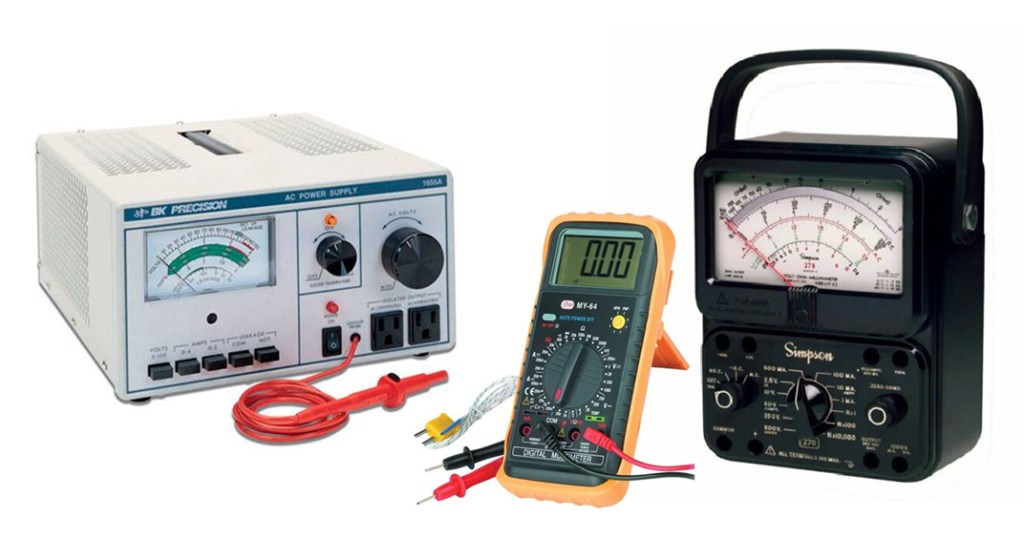
The tools needed to tune the dipole are a pair of wire snips, a ruler, and either an HF antenna analyzer, the SWR meter built into your transmitter, or a stand alone SWR meter.
An antenna analyzer such as those by RigExpert or MFJ Enterprises is a handy tool for the radio amateur. These devices transmit low power RF to the antenna and provide a reading of SWR across a selected range of frequencies. However, new these meters cost $300 and up. Your elmer or local club may be able to loan you an antenna analyzer and even help you use it.
If your transceiver has a built in SWR meter, that can be used to tune the antenna. Stand alone SWR meters are relatively inexpensive and may also be used and placed between the antenna out PL259 on the rig and the coax feedline. If you are using your rig and an SWR meter to tune, you will need to set the radio for CW or FM as you need to transmit a carrier wave to get an accurate SWR reading.
A Rig Expert or MFJ Antenna Analyzer (left, center) can be a big aid in tuning your 10 meter, dipole, but a stand alone SWR meter (right) or your radio’s built in SWR meter will also work.
Tuning Method
Raise the antenna into the air from the center insulator or balun and each of the ends. You may configure the antenna in an “Inverted V” position where each of the elements slope down at an angle of 45 degrees from the center insulator.
Take an SWR reading at 28.3 and 28.5 MHz.
Average the two readings. Ideally you are looking for an average SWR of 1.0 to 1.5.
As long as the reading at 28.3 MHz is less than the reading at 28.5 MHz, the antenna is too long. Lower the antenna and snip off 2 inches from each end of the antenna. Make sure that the two elements remain the same length.
Raise the antenna again, return to step 2 and repeat the process. Continue until the SWR falls into the desired range.
Once your dipole is in tune, you won’t have to fuss with it nor will you need to worry about using an antenna tuner. A properly tuned 10 meter dipole will be sufficiently resonant across the 0.2 MHz width of the Technician sub-band.
You’re on the air – congrats! Now what?
Now that you’ve assembled your 10 Meter station, it’s time to get on the air! But what can you do?
To help determine whether the band is ‘open’ or not, you can listen for beacons. Becaons are weak signal stations (less than 20 W, more commonly 1-3 watts) transmitting from various locations around the world – if you can hear the beacon, the band is open between you and the QTH of the beacon station. You can find a list of 10 Meter beacons here. Check out the Official SWL Channel video “What are 10 meter beacons?” to learn more.
On the air, you will find much to do on 10 meters. Beyond the anticipated DX openings due to Sporadic E and the increased solar activity from Solar Cycle 25, you will find special event stations and contests on the 10 meter band. Many of these events are produced and promoted by Ten-Ten International, a global organization first founded in 1962 in California, that promotes 10 meter activity and good operating procedures.
Membership in 10-10 is easy to achieve – all it takes is working and collecting the 10-10 number of ten members, plus $15 annual dues. In addition to programming on air events, 10-10 also publishes a quality quarterly, 10-10 International News.
The MARC/Castle Craig 10-10 Chapter holds a weekly net every Tuesday night at 8:00 pm local Eastern time at 28.375 MHz. Everyone is welcome to check in! If you’re not in the New Haven locale, look for 10 meter nets in your area. There are many out there, you may be surprised to find an active group near you.
In Conclusion….
I hope you found this article informative and useful. I hope it may have inspired you, whether you are a Technician or hold a higher level license, to get on 10 meters and enjoy the anticipated DX in the next few years. Spread the word – 10 meters is coming back!
Feel free to drop me at james@ab1dq.com if you have questions or wish to provide feedback.
It had become a long running joke with my wife Ellen, and her best friend Naomi, who has been coming over for socially distant weekend visits ever since lockdown began in March. When Nay would arrive most Saturdays around noontime, she’d find me outside with my head stuck under the dashboard of my 2012 R56 MINI Cooper and she’d ask Ellen if I was ever going to finish my car project. Truth be told, it really wasn’t ‘one’ car project that I undertook during my summer of Covid, but several automotive upgrades. The focus of this post however, is the installation of two transceivers to create my new mobile “ham shack.”
A SIMPLE PROJECT EVOLVES
It all started when I decided to replace a blown factory speaker. Well, speakers are sold in pairs and why upgrade the front speakers only? Soon a package arrived from Crutchfield with a complete set of premium aftermarket speakers.
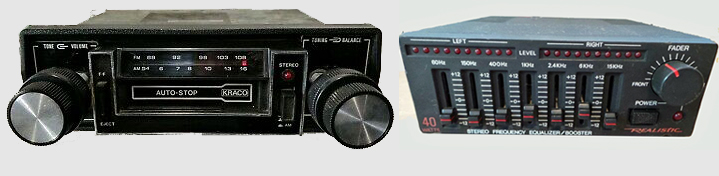
Replacing the speakers took me back to my teen years when I installed that Kraco Dashmsater AM/FM/MPX stereo that I bought at K-Mart for $30 in my Ford Pinto along with matching 5″ Kraco slimline speakers mounted in the cardboard rear deck. That Christmas mom & dad made my holiday by getting me the Realistic 40-watt amplifier and graphic equalizer complete with 7 sliders and flashing LEDs that I ‘needed’ to complete my ride! (You can bet your figgy pudding that I was outside right after Christmas dinner in the subfreezing weather with my wire cutters and electrical tape racing to complete my hi-fi upgrade before sundown!)
The heart of my first car stereo install, circa 1982
So feeling nostalgic, I didn’t stop at the speakers and soon a reasonably priced Kenwood eXcelon DPX594BT double-DIN stereo had also arrived from Crutchfield with bells & whistles that I couldn’t have imagined in my Kraco Krankin’ days – SiriusXM, Pandora, Spotify, Alexa, Bluetooth, USB, a CD player and of course good ole AM/FM.
The second-generation MINI Cooper features a big ole Speedometer in the middle of the dashboard and the bottom half of that speedometer is where MINI incorporated the factory radio display and memory buttons. The aftermarket stereo dash kit came with a blank out panel for the factory display and buttons, but this left sort of an unfinished empty look right in the middle of the dash.
MINI R56 Speedometer blanked out for after market stereo installation…. A lot of prime empty space!
And this my friends, is where the inspiration came in. That big empty space looked like prime territory for a transceiver faceplate. A couple of years ago I purchased a Yaesu FT-891 with the intention of building a Go-Box that I hadn’t done anything with. I saw that the Yaesu remote head and mounting bracket could neatly be attached to the speedometer blank out plate and this would be an excellent use for the space. The ‘bug’ bit hard and before you knew it, I was all in on making this happen.
HOW IT ALL CAME TOGETHER
I decided to install not only the HF rig, but also my Alinco dual band UHF/VHF DR735 and I began the project by bolting both radios to the back of the rear passenger seat, with plenty of slack cable so the rear seat could be folded down. I routed the control head cables under the door sills under the edge of the carpeting and on up to the dashboard. So far, so good.
The two transceiver bodies bolted to the back of the rear right passenger seat. The HF Yaesu FT891 is above the 2M/440 Alinco DR735. Cables are held in place, stabled to the seat back, with plenty of slack to allow the seat to be easily folded up and down as needed.
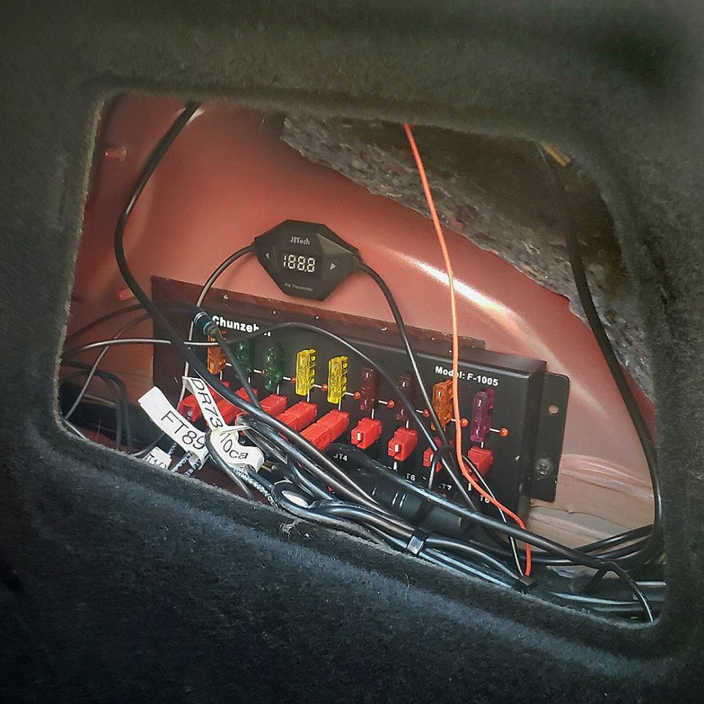
To power the radios, I ran a 10 AWGdirect line from the battery, through the firewall and under the center console back to the trunk area. The MINI has a nifty little carpeted access panel for access to the taillights so I used that space to mount a PowerPole distribution block at the back of the car to not only power the two rigs, but to provide a convenient place to plug in any other 12VDC gear I might want for a future outdoor radio event, say Field Day.
One concern that arose was that both radios had speakers built into the radio bodies, which were now in the trunk. Not so good for this old fart with failing hearing. I thought about adding an accessory speaker on the dashboard, but in such a small car, space comes at a premium and I’ve already cluttered things up with two new remote heads and microphones.
I decided to try a creative solution and bought one of those cheap-O FM modulators that let you transmit audio from your MP3 or CD player to your car stereo. I mounted the tiny modulator above the PowerPole block, connected it to the radio audio output jacks, and tuned it to 89.3 MHz, an unused frequency in my area. I programmed one of the FM memory buttons on the new Kenwood stereo to that same frequency, and now I get my ham radio audio through the stereo speakers.
Here you see the power distribution block and the FM modulator above it, bolted to the inner rear fender and neatly concealed under the removable access door in the trunk area.
For antennas, I went with the Yaesu ATAS-120 screwdriver antenna for HF and installed a lip mount on the rear tailgate. I was fully prepared to drill through the roof for a better mounting position with a much better ground plane, but my car has dual sunroofs – so that wasn’t a very viable option. On the other side of the tailgate you will find the 2M/70cm dual band antenna attached by another lip mount.
A MINI Antenna farm… two lip mounts, with an ATAS-120 screwdriver antenna on the driver side and a dual band 2M/70cm antenna for local FM on the passenger side. The MINI’s dual sunroof precluded the option of drilling a better situation HF antenna mount into the roof. The HF antenna placement may need to be revisited…
The last time I had a mobile installation was about a dozen plus years ago when I installed a Yaesu FT-857D in my 2002 Ford Focus sedan and used a four-magnet trunk lid mount with interchangeable mono band ham-sticks. I did have a lot of fun in those days working into Europe on 20 and 40 M after work while stuck in the parking lot that is rush hour on Route 128 outside of Boston.
When I did the Focus install, I took the matter of bonding seriously and used copper braid to bond the doors, hood, hood, and rear hatch to the main body. However, realizing that all of the doors should have a good ground by means of being bolted to the body, I haven’t yet bonded the doors on the MINI This SEEMS logical, but I don’t know – I welcome your insight and feedback here. I did add a beefy ground cable from the antenna mount to the rear hatch sheet metal for a better ground.
AB1DQ Mobile operating position – the control head for the FT891 looks like it was designed for its placement on the MINI R56 speedometer, and the Alinco DR735 control head fits neatly under the ignition key slot. Yeah, I splurged for a Heil mobile microphone too!
HOW DOES IT WORK YOU ASK?
So far, so good – I have made some initial HF contacts on 40M along the east coast and into Nova Scotia, have checked into ECARS on my morning errands, and I have also participated in the local Meriden Amateur Radio Club Tuesday Night 10M net.
I’m pleased so far with the performance, but I have discovered that the ATAS antenna tunes slowly – I may need to beef up the ground connection on the lip mount – and of course it’s placement is far from optimal. I may try some of my ham sticks left over from my first mobile installation with a mag mount on the roof to see how it compares. So far I’ve not noticed significant alternator/engine noise on receive, nor have I received any audio reports indicating whine on my signal. I did notice, however while transmitting on 10M, it causes the LCD screen built into my rearview mirror to flutter.
The bottom line is I’m quite pleased so far and look forward to making any necessary tweaks going forward as I make more contacts with my motorized MINI go-kit!
EPILOGUE… WHAT ELSE DID I DO TO MY MINI?
I mentioned that I did several upgrades/mods to my MINI Cooper this summer, besides the radio mods detailed above. In addition to the radio projects outlined above, here’s a list of the additional things I did to “Hubert,” my 2012 R56 MINI Cooper this summer…
I installed a Rockville RW10CA 10″ 800 Watt Slim Low Profile subwoofer in the trunk. I had underestimated the size of the subwoofer. Despite the words “slim” and “low profile” in the product description, I discovered it did not fit under the front seats, as originally planned and it occupied a lot of the limited available trunk space. My solution was to make it easily detachable and removable using PowerPole, RCA and RJ11 connectors.
I upgraded the horn. The car came with a very “un-MINI” trumpet horn set, and one of the two horns wasn’t functioning. I replaced the anemic horn with a FARBIN Loud Car Horn Super Tone 12V High Tone/Low Tone Metal Twin Horn Kit. Not only is it louder and grabs more attention, my MINI now has a more appropriate “meep-meep” horn sound.
I installed a pair of Wipac 5 1/2″ driving lamps. I always liked the way auxiliary driving lamps looked on both the classic and new MINI. I saved a significant portion of the cost by choosing Wipac over MINI lamps. The MINI lamps are expensive and make use of a proprietary mounting bracket that will not accept other manufacturer lamps.
I also attempted to upgrade the headlights. Like many MINI R56 owners, I felt the OEM halogen lamps were too weak. I purchased a set of aftermarket extra-bright LED low/high beam bulbs. The bulbs were simple to install, however the new LED headlights flickered incessantly. Apparently this is a fairly common occurrence that can be resolved by adding a resistive ballast to the circuit. I purchased a plug and play ballast set but was saddened that it did not completely resolve the flicker issue. So I’m back to the OEM headlights for the time being.
Twenty years ago this August, I played a small part in starting an Internet photography thing, that frankly I’m surprised has lasted so long.
Along with a few internet friends in an online camera group, the Argus Collectors Group, we sought to start an annual “Argus Day” to celebrate and promote this beloved brand. Participants in Argus Day would be encouraged to take their favorite Argus camera with them wherever they went that day to take photographs and to spread Argus awareness. The ACG would publish submitted photographs taken on Argus Day in an online gallery.
With an eye to making Argus Day a little more distinctive and just a bit quirky among the various film camera days, it was decided that instead of occurring on the same day each year, each subsequent Argus day would occur one year + one day from the previous year’s observance.
The first Argus Day was held on Argust (August – ha!) 1st, 2001. The second was on Argust 2, 2002, the third on Argust 3rd, 2003, and so on. As I mentioned, this year marked the 20th edition of Argus Day, and accordingly, it rightly fell on Thursday, Argust 20, 2020.
My Story
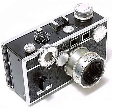
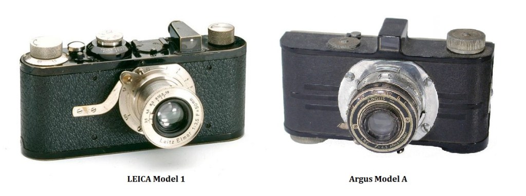
My first 35mm camera – the Argus C3 “Standard” – circa 1966
My love of Argus cameras began when I was 12 or 13 years old when dear old dad, handed down his old Argus C3 Standard rangefinder camera to me. Dad loved photography and shot some amazing Kodachromes during his two hitches in the US Army while stationed in Greenland and then in Germany. Dad only shot slide film and the sensory experiences of those special nights when he’d come home from work with a new set of slides from his most recent completed roll of film remain etched in my memory to this day – the bright yellow Kodak box of slides, the dusty smell of the portable projection screen, the ker-chunk of the carousel projector.
Dad, a frugal man, never sent a roll for processing before it was completely exposed so some times we were viewing Easter slides, while seeing the prior year’s Christmas shots at the same time. The best slide shows were the nights when dad would honor our request and show slides from his Army days, or when he was sparkin’ mom. The images were color saturated and beautiful and it was fun listening to dad and mom recount those earlier days.
Prior to receiving my C3 from dad, I had cut my teeth (photographically speaking) first with mom’s old Kodak Brownie Hawkeye box camera when I was nine or ten. From there I moved on to using a Kodak Pocket Instamatic in junior high school. The Kodak took photos on the then ubiquitous and pretty inferior 110 film cartridge. I remember taking that camera on my 8th grade field trip to Washington DC. Pretty much all of my classmates were carrying similar low-end110 cameras from a variety of manufactures.
Dad was pleased with my composition of those DC snapshots and told me that my good work merited his old Argus. Wow! I was thrilled…. finally a “real” camera – with all the proper adjustable settings – aperture, shutter speed, and focus!
Of course, the Argus was more than a little outdated by the late 1970s when I received it. By that time there was a growing variety of high quality consumer single-lens reflex cameras available with superior optics and advanced electronics including the Canon AE-1, the Nikon FM, the Olympus OM-1.
By 1978, the time of the rangefinder camera had already come and gone, and in fact, at the time when my humble Argus “brick” was new in the mid-1960s, Japanese manufacturers had already redefined what a 35mm rangefinder camera was, offering a plethora of more feature packed compact rangefinders in smaller and more ergonomic bodies.
Compare the mid-60s Argus C3 Standard alongside the Canonet QL19.
TIRED (L) : by the mid-60s, the Argus C3 rangefinder was nothing but a cosmetic rehash of a 25 year old design which featured a separate rangefinder window, a slow f/3.5 triplet lens, no metering, and a three leaf shutter with a top speed of 1/300 (give or take). WIRED (R): The Canonet QL-19 was more compact and lighter than the Argus “brick” and boasted a wealth of technological advances including a fast f/1.9 lens, built in self-timer, a film-plane shutter with X-sync to 1/500 sec, and CdS cell metering with aperture priority EE.
Yes, I would have loved a Canonet or Yashica Electro, but I was only 12 years old and my only disposable income came from my weekly allowance. I truly loved my Argus and I took it everywhere with me for the next several months until the flash sync started malfunctioning. Then, once again, dad came to the rescue as I started high school – handing down an even cooler vintage camera – his old East German manufactured Ihagee Exa SLR. Perhaps that will be subject of a future blog post. But for now, back to Argus…
What’s an Argus?
Given the important role that the Argus camera played in making 35mm the popular film format it because, it’s somewhat sad that more Americans don’t know much about Argus.
The Argus camera came into being in the mid 1930s, when Charles Verschoor, the president of IRC, the International Radio Company in Ann Arbor Michigan saw the compact Leica 35mm candid camera while in Europe. Before the advent of the 35mm film cassette, the camera the typical household was most likely to own was a either a simple medium format box camera like the Kodak Brownie, or perhaps a simple folding camera like the Ansco Readyset. They were not compact, they were not particularly easy to use, and they typically didn’t produce high quality images.
IRC was a manufacturer radio receivers and had established a sweet niche in that market producing ‘compact’ Kadette radio sets many of which were housed in cabinets made of primitive plastics, such as Bakelite. But radio sales were highly seasonable – up in the winter months when families stayed indoors and radio propagation conditions were better, and down in the summer months when more folks were out of doors and radio reception was poor.
Verschoor was looking for a second product line to help level out the annual revenue stream for IRC and the new 35mm camera seemed to fit the bill. IRC’s collaboration with existing plastic firms would be beneficial providing a source of inexpensive sturdy and lightweight bodies for their cameras.
In 1936, IRC introduced the Argus Model A, and the rest, as they say, is history. It was an instant success, selling 30,000 units in its first week. Argus quickly introduced a variety of other models with more features, including the Argus C line of rangefinder cameras, first introduced in 1939, which featured a built in rangefinder to set the focus.
It’s almost impossible to overstate how responsible the Argus camera was for making 35mm photography as popular as it became. If you wish to learn more about the Argus A and how it changed photography for the every man, I highly recommend Hrad Kuzyk’s free book, 35mm for the Proletariat. For a deeper dive into the company and it’s photographic products, get a copy of Henry Gambino’s 2005 book, Argomania: A Look at Argus Cameras and the Company That Made Them.
The Leica was the ultimate gadget but with retail costs topping $200, it was a luxury item for the rich. The Argus Model A was introduced in 1936 with a MSRP of only $12.50
But what is the Argus Collectors Group?
At the dawn of the interwebs in the mid-90s, I discovered out this new thing called eBay where you could bid on and buy all sorts of nostalgic treasures from your past – things you had long since discarded as ‘junque.’
It didn’t take long for me to acquire a new used vintage Argus C3 camera and I was magically transported back to my childhood. I started taking my new brick with me everywhere, and found it was quite the conversation starter. I remember showing it to my dad on one of my visits home, and he just smiled and laughed when he saw it – it brought back fond memories for him too.
At the same time, I came across an internet SIG called the Argus Collectors Group, a global virtual community of similar Argophiles who were obsessed with their Argus cameras.
What a group! I learned much about Argus history from that dynamic community while making many good friends. The group was created as an offshoot of the IDCC, the International Directory of Camera Collectors. Noted Seattle camera collector and historian, Bob Kelly, was our group’s moderator at the time I joined. When he retired from the task, I took over the role for a couple of years before passing the mantle on to Wesley Furr, who has provided steady leadership ever since.
The ACG remains a very active and dynamic group and continues to grow to this day. Over the years, this close-knit group has undertaken a number of projects and programs, including an annual Holiday Lights photography contest, and the Argus Argosy, where members passed a single Argus camera from photographer to photographer from around the world to make a global online gallery.
The ACG’s premiere annual event is the ACG Gathering, organized by Ron Norwood and our late and sadly missed friend Doug Wilcox. The Gathering was first held in Martinsville, VA in 2001 before taking up residence ever since in Eden, NC. Today the ACG is closely affiliated with the Argus Museum in Ann Arbor, which also hosts an annual Argus Conference each October.
Argust 20, 2020
I end this post sharing some of the photographs I made this year on Argus Day. You will be able to see my two submissions, along with my wife’s and many other photographs from the many talented ACG members online here going all the way back to the second Argus Day (sadly, the first Argus Day gallery was lost when we changed host servers.)
Ellen and I have been fortunate enough to be able to continue to work from home during the Covid 19 pandemic, so this year we both participated from home. She photographed our gardens with an Argus 75 box camera while I took a lunch time walk around our hometown of Cheshire, CT with my favorite C3, a 1948 seven speed variant, serial number 233428 loaded with Ilford Pan F+ 50. I developed our film with Rodinol, scanned the negatives and then tinted them in Photoshop.
I welcome your comments and feel free to drop me a line at james@ab1dq.com. Thanks for looking!
Material for this blog post was originally presented on the Meriden Amateur Radio Club Tech Net, on August 20, 2020, a 2 meter net held on the first & third Thursdays of the month on the W1KKF, 147.360+ MHz repeater in Wallingford, CT, and simulcast on Zoom.
My love of amateur radio goes all the way back to childhood when I would waste hours in my grandfather’s workshop in our basement building Radio Shack Science Fair kits and mucking around with all the dead radio and TV carcasses he accumulated. I have been melting solder for the better part of my life and to this day still love building kits and recapping, repairing and realigning vintage radios.
However, my skills have never been great… I lack what many employers have rudely called an “attention to detail.” All these years later, I’m sorry to say that still the majority of things I put together don’t initially work as they should.
I used to get discouraged but then realized this was actually a gift – – – instead of abandoning a non-functional project, which would make it a waste of my time and money, I have discovered the process of troubleshooting actually gives me more bang for the buck.
Troubleshooting requires a deeper dive in order to learn and understand how the circuit works which reinforces my electronics knowledge. Finding and fixing a malfunctioning piece of equipment is also very satisfying and rewarding – it’s like solving a puzzle, but in the end you get something you can actually use.
In this blog post, I’m going to cover some of the basics – including essential tools I use and the steps I take when tackling a new troubleshooting project.
Disclaimer – I am by no means an expert, I believe I’ve made that clear. What follows is intended to be foundational and inspirational to others who have been frustrated when troubleshooting electronic appliances. More advanced techniques dealing with specific circuits is beyond the scope of this post. Look for future posts dealing with more advance RF troubleshooting topics.
THE ESSENTIAL BENCH TOOLS
The most basic tools you will need for troubleshooting include:
A good stable bench power supply You might be surprised the number of electronic problems are due to no or insufficient juice, reversed polarity and blown fuses.
A quality Volt-Ohm-Meter (multimeter) is essential for measuring voltages, current and resistance values. Today the majority of meters are digital and there are many serviceable units to be had for an inexpensive price. A good workbench should have both digital and analog meters. Analog meters still have an edge over a digital meter in certain circumstances such as when reading fluctuating signals (current), as digital meters typically give you an average reading. This is an advantage when trying to peak a tunable circuit.
Essential to every workbench today – magnification tools.
Good magnification is essential for troubleshooting, especially when working with today’s miniscule parts and circuit boards with surface mount components. Either a good magnifying desk lamp, or a plug-and-play USB Microscope that plugs into your computer is going to be invaluable. Like very one else who has made it to middle age, I have experienced waning vision (which pretty much sucked since ever since I started wearing glasses at age 2), and dexterity. I got my magnifying desk lamp on Amazon and my USB microscope from QuickSilver Radio, a favorite source for ham radio cables, small parts and tools. TECH TIP:In a pinch, your cell phone can be used to provide quick and dirty magnification. Simply use the camera to photograph the part you need to magnify then open the photo and zoom in – we are living in a Golden Age, my friends!
Temperature controlled soldering iron and tools. This is not an area to cut costs. Growing up I soldered with inexpensive solder irons from Radio Shack, seldom concerned with what their wattage ratings were – 15? 30? 45 watt? – Whatever it takes. I have learned in recent years the importance of a good temperature controlled solder station as well as the importance of using the correct iron tip for the application. This upgrade has been a game changer improving the quality of my solder work, while reducing my stress and frustration. It’s important to not use too much heat when working with delicate components and circuit boards, and it’s equally important to use too little heat when soldering joints.
TROUBLESHOOTING TIPS & TRICKS…. FIRST THINGS FIRST
The very first step in attempting to diagnose electronic equipment failure is to clearly define the problem., that is, what specifically is not working and also importantly, what else isn’t working?
Create a list of all symptoms and indicate whether the symptoms are intermittent. If intermittent, does the symptom occur when a specific control is activated? Does the problem stop if the appliance is moved or re-positioned? Once you have a list of symptoms and circumstances, evaluate the list – which symptoms might be linked? Where is there commonality to what is failing? Documenting and understanding all the symptoms can be useful.
The second thing to evaluate is the power situation. Technicians who do a lot of troubleshooting identify lack of power as the number one reason why a piece of equipment isn’t working. Sounds simple, but the question “Is the unit plugged in?” is foundational.
Make sure there is a fuse in the fuse holder, and that it isn’t blown. If it is blown, it will take more than just replacing the fuse, but you will know that something is awry with the power circuits – either a short or a failed component creating an overdraw of current.
Make sure that DC polarity is correct, and make sure there aren’t any broken power leads, disconnected power connectors, or cracks in the circuit board or broken traces around the power supply circuit.
After assessing the power supply, next up is an in depth visual inspection – this is where the magnifying tools come in handy. Carefully inspect both sides of the circuit board looking for obvious issues such as:
Missing components
Damaged/burnt out components
Broken traces
Cracked boards
Signs of previous ‘work’
Obvious mods, parts replacements
Excess flux, solder blobs and cold joints
Some of the many problems to be discovered during a visual inspection.
TIME FOR THE DEEPER DIVE
If your circuit is getting proper power and you didn’t find any obvious problems after a thorough visual inspection, it’s time for the deeper dive. This will involve gathering, reading and understanding all the circuit documentation you can get a hold of. This documentation includes:
Schematic Diagrams
Block Diagrams
Chassis and Parts Layout
Manufacturer Manuals and Supplements
Third Party Manuals ( e.g. Riders, SAMS PhotoFact)
Component Data Sheets
The internet makes so much information available to the troubleshooter, most of it free. These resources include You Tube and online forums. (QRZ, Yahoo, Google groups, RadioMuseum.org), various manufacturer websites, and instructional sites such as All About Circuits.
Don’t forget about local resources, namely your local amateur radio club where you will find numerous older and wizened “Elmers” who are generally happy to pass on their expertise.
My local amateur radio club, The Meriden Amateur Radio Club here in Connecticut runs an open house every Saturday morning at the Wallingford EOC where we are headquartered. The open house features a repair bench staffed by the likes of NZ1J, Dave, KE1AU, Bob, and WB1GYZ, also Bob, who are always up for a new challenge.
Saturday open house workbench activities at the Meriden Amateur Radio Club
WHAT’S CURRENTLY ON THE AB1DQ WORKBENCH? (a troubleshooting case study currently in progress!)
Earlier this summer I constructed the MFJ 9340 40 meter QRP Cub Transceiver kit. This kit was not unlike many others I have built in the past including the WA3RNX 40 meter transceiver, and the Wilderness Radio SST 20 meter transceiver kit. The MFJ kit came with a circuit board pre-populated with all of the SMD components and required the builder to install the traditional through the hole parts.
Construction went smoothly over two or three evenings and I was happy to find that I had no ‘spare parts.’ (A good sign.) I was able to align the receiver easily per the directions in the construction manual, however when I attempted the transmitter alignment, I ran into trouble. What happened?
I started troubleshooting with a good visual inspection focusing particularly on the solder side of the board looking for bridged solder joints. Nothing looked suspect.
Because this was a kit radio, I had just about all the documentation I needed in the manual to start trouble shooting including the Block and Schematic Diagram, a diagram of component lay out, and a page of Troubleshooting Tips too.
I started with these diagrams and breaking the radio down into separate functions and began color-coding the schematic, block diagram and parts layout. This took a bit of time, and you could argue it wouldn’t be necessary for a simple transceiver, but doing so did provide me with a solid understanding of how the radio was designed and where I can set my focus for finding trouble….
My color coded block diagram of the MFJ 9340 which ties to……my color coded schematic, which also ties to……my color coded Parts Layout.
So now I know where the sub-assemblies and their parts are located on the circuit board, and I can trace the stages of the circuitry on the schematic, great! Now I need to go even deeper to see if I can find where the problem is originating.
The MFJ documentation had a table of voltages for each of the transistors and ICs. I am always thrilled when I can find a voltage table like this or see that proper voltages are indicated on a schematic.
I created a simple Excel spreadsheet with the MFJ data and carefully measuring the test points on my radio, I was able to calculate unit and percentage variances which allowed me to find trouble spots.
My Excel Table of specified voltages vs. my measured voltages.
I quickly identified hat the biggest variances were found on Q6, the Transmitter Driver, U5 the Transmitter Oscillator chip and Q5 the Transmit buffer. None of that was a surprise since I knew my problem involved the TX function.
However, I also observed a sizable variance on the BFO buffer, Q4, which might be related…
[SLIDE 16] I marked the over/under voltage readings on my schematic and cross referenced the parts layout to determine where I needed to focus. These parts were pre-installed, so I worked backwards from each in the circuit to look closer for problems.
Red indicates where the under-voltages are occurring…
WHAT’S NEXT AND SOME KEY TAKEAWAYS
This may seem like a strange place to end a blog post, but as of the time this material was presented on the MARC Tech Net on August 20, 2020, I had not yet finished my troubleshooting work on the MFJ Cub.
Next steps on the project will be to trace back ‘upstream’ from the variances on the schematic and closely examine my work, verifying that I placed the proper components where they belonged, and that my solder joints are good – not cold, and not blobby and bridged. I also want to take a close look on the two torrid inductors in the TX filter, L10 and L11.
While I had hoped and planned to have completed my work on the Cub prior to the net, I was unable to, and that’s my final lesson for now.
When troubleshooting, don’t rush and don’t get aggravated. Take it slow, work methodically and logically. Never jump to conclusions at the first sign of something unusual too. Many times the problem isn’t obvious and many times too, it’s not complicated. Stick to it and in the end you will find yourself rewarded with a satisfied sense of accomplishment.
As for me, I will update my blog when I have discovered and resolved the problem with the MFJ 9340. Watch for that post, or feel free to shoot me an email if you have questions, suggestions or want to discuss further.
GENERAL TROUBLESHOOTING TIPS
I mentioned that this material was originally presented during a 2 meter net. I want to thank the following stations who checked into the net, and I will close with some bulleted advise, tips and tricks that were shared by the participants…