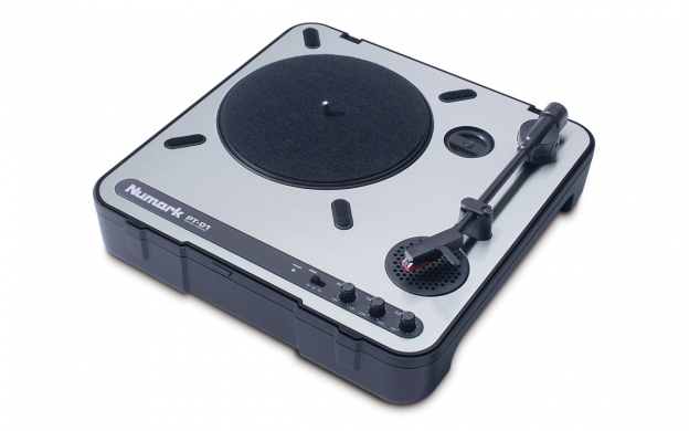
A couple years ago I purchased a Numark PT-01 portable record player after reading and watching some reviews online. Fully aware that portable record players don’t come close to delivering the high fidelity of a good home turntable set up, I wanted something I could use to play records while sitting out on the porch in the evening.
There aren’t many options in portable record players, and the vast majority of what is available are all based on the same cheap plastic architecture featuring a Chuo Denshi ceramic cartridge. The Crosley Cruiser in all its varieties is ubiquitous as are the Victrola clones. Neither are renowned for their high fidelity and are panned by most ‘serious’ audiophiles.
While the Numark PT-01 features the same cheap plastic mechanism belt driven by a DC motor as the Crosleys and Victrolas, but had some attractive features not found in those players. The Numark has an adjustable tone control and a pitch control, two were nice pluses, but even better, the PT-01 can be powered by six D-cells, unlike the Crosley and Victrola portables that must be powered from a wall wart transformer.
The PT-01 only has a monaural full range 3″ speaker, but to my ear, that’s a better choice than the smaller stereo speakers mounted too close together in the Crosley and Victrola. LIke the Crosley and Victrola, the Numark does have RCA jacks for full stereo out, and two headphone jacks – both 1/8″ and 1/4″ – which surprisingly produces very decent sound when a good set of stereo headphones are use.
Playing records on the PT-01 on the front porch has been absolutely delightful over the past two years, and I was so impressed with this $100 portable player that I had gifted one to my 8 year old godson and 12 year old granddaughter. Both children have enjoyed the record player and both continue to grow their record collections.
The Numark PT-01 portable record player
Modifying the Numark PT-01
The PT-01 has something of a cult following and is also available in a ‘scratch’ version. Several aftermarket firms have marketed modifications for the PT-01 and as someone who enjoys mucking around with electronic devices, I found myself unable to resist the allure of making a few mods to my record player.
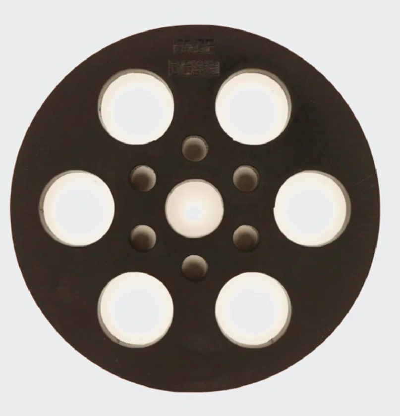
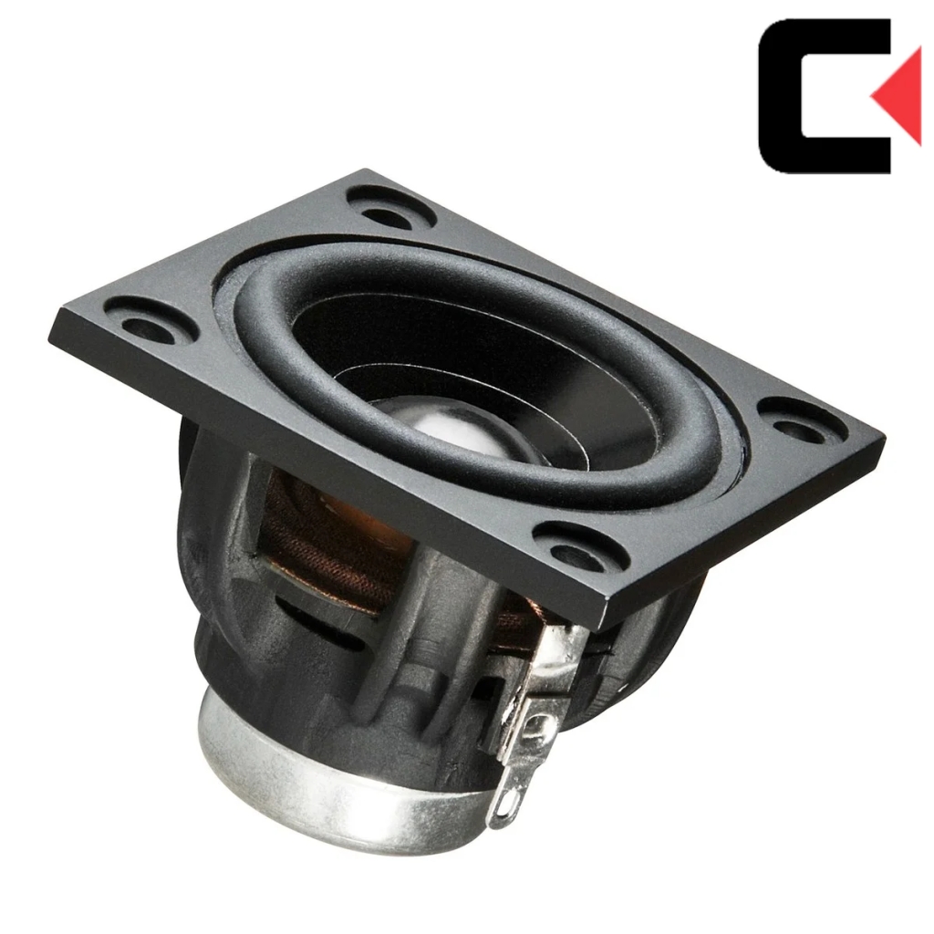
This weekend I installed a better speaker, the Jesse Dean Designs Puck-It platter support and PCB tone arm & pre-amplifier kit to allow me to use a magnetic cartridge.
The speaker was an easy upgrade, as the speaker has the same dimensions as the stock speaker. The Puck–it platter support, which adds rigidity to the plastic platter was also a simple upgrade, as it just firmly presses into the center of the bottom of the platter.
The Jesse Dean Designs Puck-It Platter support (L), and the Celestion replacement speaker (R)
The installation of the new tone arm was a bit more involved, but again, wasn’t difficult, and my installation took about a half hour’s time on the workbench guided by the excellent Jesse Dean YouTube step-by-step directions found here.
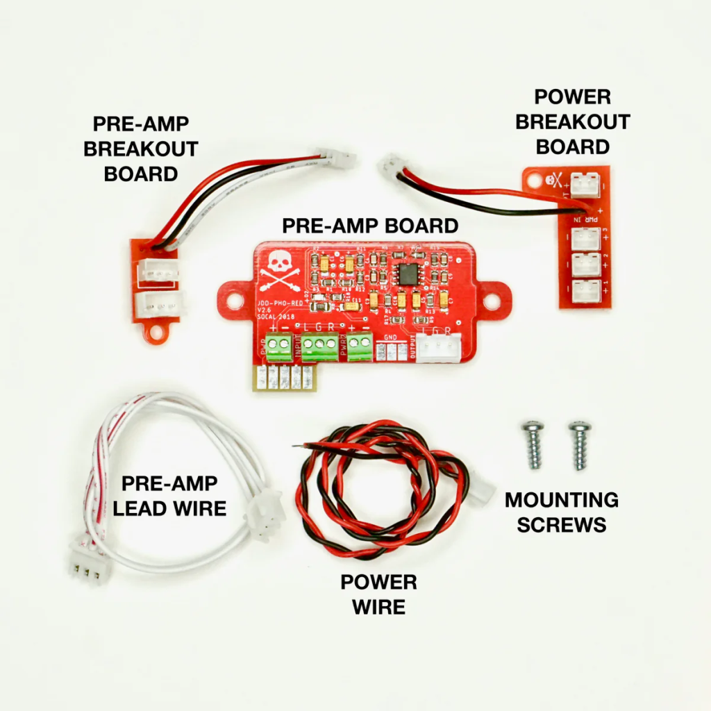
The tone arm kit comes with everything needed for the mod including, in addition to the tonearm itself, a compact pre-amp, two breakout boards, connection wires with connectors and hardware.
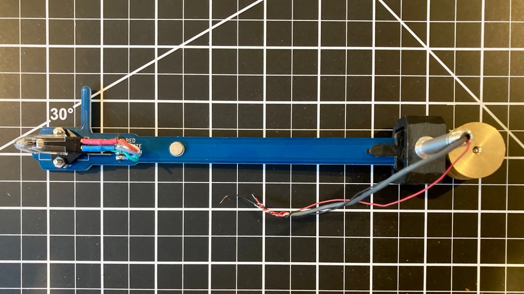
The tonearm is a bit unconventional and a thing of beauty. It’s actually a printed circuit board, which allows it to be thin and connections from the cartridge to the back of the arm are built-in as traces on the board. It also features a nifty built in white LCD under the head shell area.
The bottom of the flat tone-arm
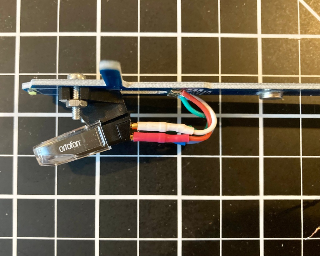
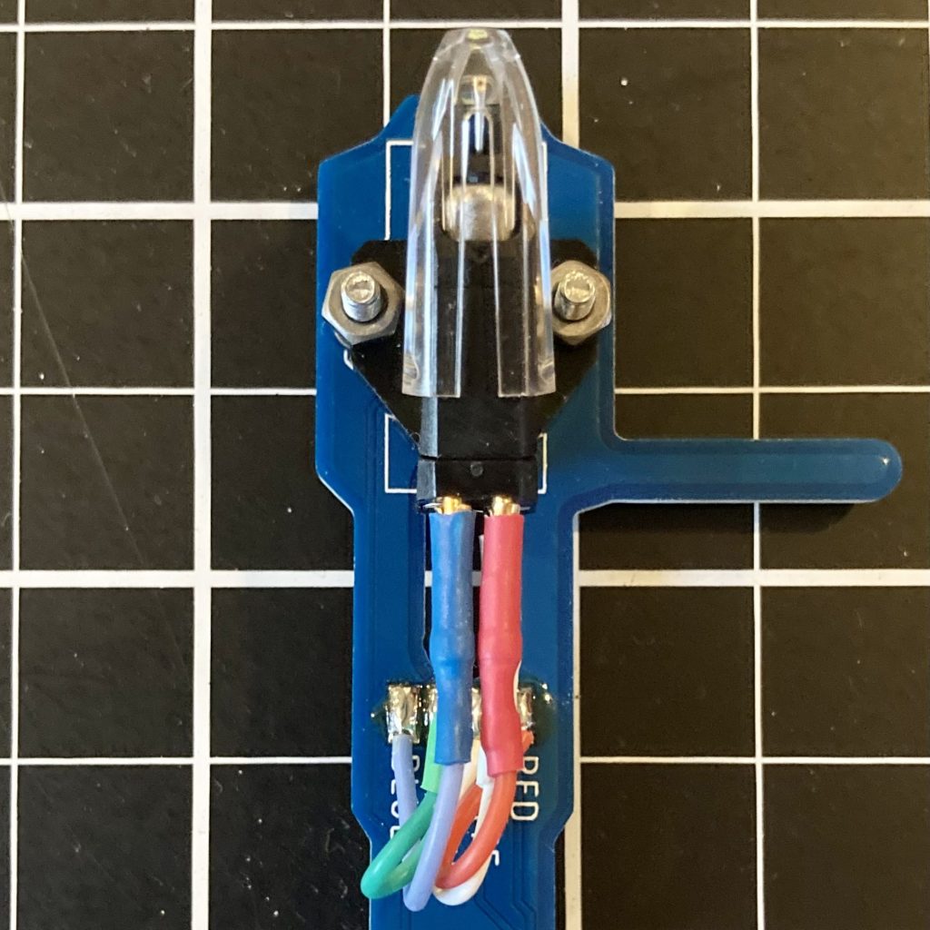
The Ortofon OM 5e cartridge mounted to the PCB tone arm.
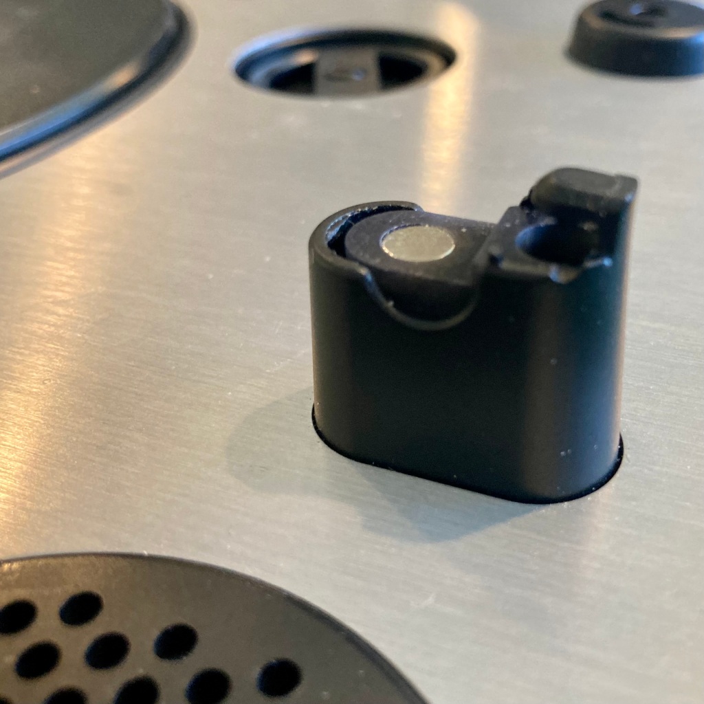
L: Bottom view of cartridge mounted to the tonearm. R: The Jesse Dean kit comes with a nifty magnet insert that goes into the original tone-arm holder. A very cool design, indeed!
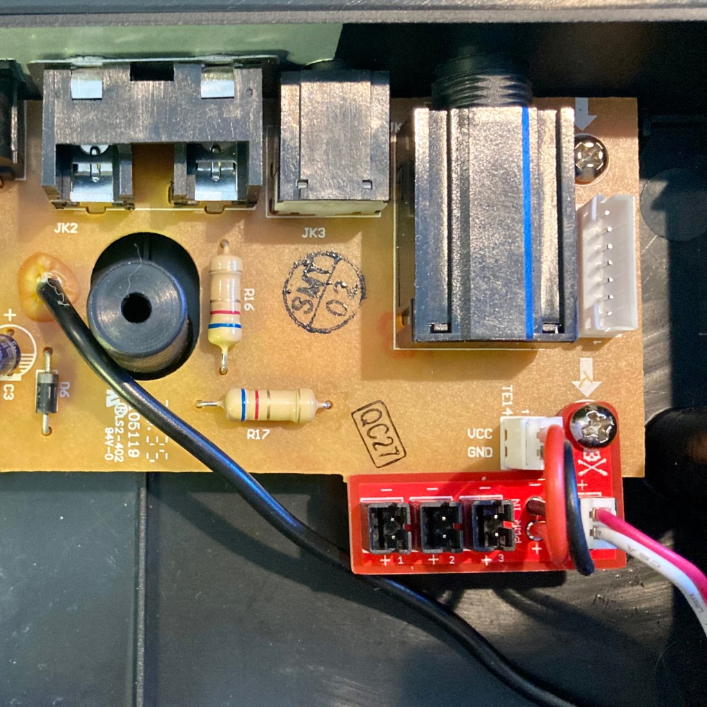
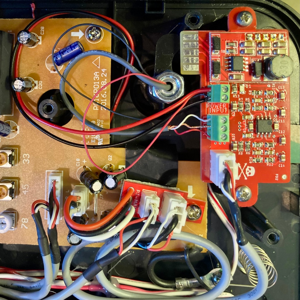
The accessory boards needed for the pre-amp are very well engineered to fit into the existing PT-01 architecture without the need to drill additional holes. Each of the three boards mounts neatly using existing screws.
I did, however encounter a very minor fitment issue when installing the pre-amp break out board. I could not mount it square to the existing PCB as two electrolytic capacitors interfered with the end of the break out board. It was no matter to mount the board slightly counterclockwise on the mounting screw axis. This was the only glitch I ran into when installing the tonearm kit. It was an easy and relaxing project to work on on an Easter Sunday afternoon.
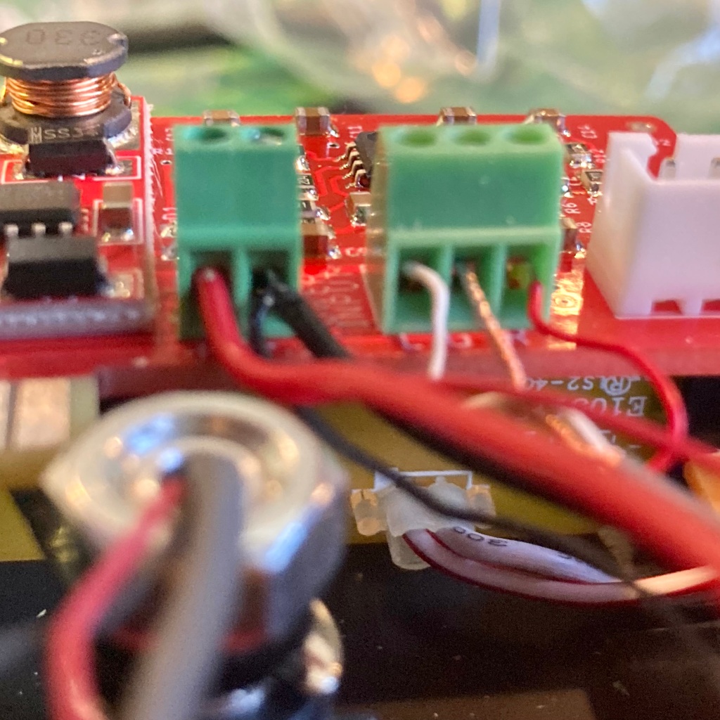
L: The power break-out board installed in the bottom half of the PT-01 cabinet. C: The Pre-amp board and pre-amp break-out board installed. (Note there was insufficient room to mount the break-out square to the main PCB due to the placement of two electrolytic caps). R: The power and tone arm connections on the pre-amp board.
Results
Powering up the PT-01 for a test run before closing up the cabinet, I found that everything worked properly. I queued an album and made sure to listen on a set of headphones to make sure I was getting stereo L/R audio, something that wouldn’t be obvious listening through the monaural speaker if one of the channels wasn’t properly connected.
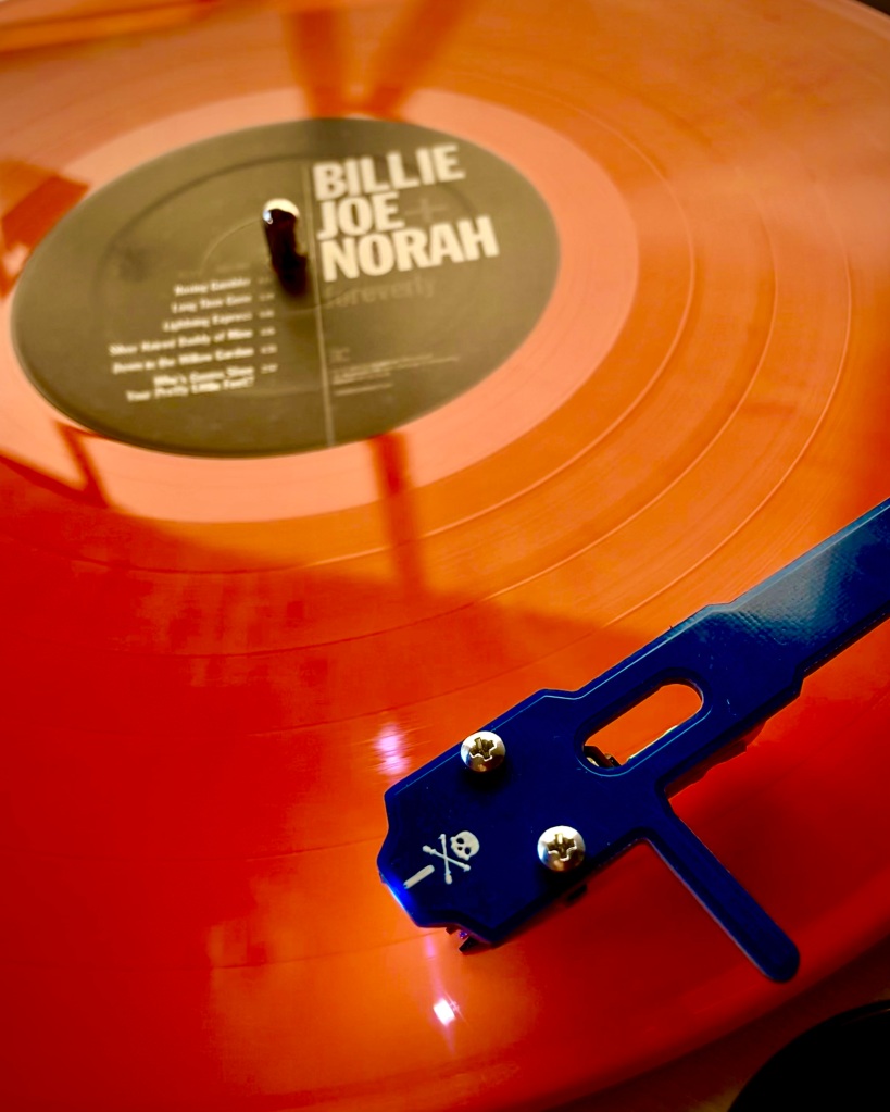
It works – huzzah!
Overall, I’m very pleased with the results. As expected there is a much improved higher fidelity sound due to the replacement of the ceramic cartridge with the higher end Ortfoon moving magnet cartridge. It’s definitely not audiophile quality, which is to be expected, but for the cost of these few accessory parts, my beloved portable record player has been appreciably improved. And, here comes summer!
This past week I had the opportunity to glom onto a business trip my wife was taking to San Francisco on the cheap. As her travel and lodging was being covered, I was able to enjoy a mini-vacation for the cost of an airplane seat – not too shabby!
As we have visited San Francisco a couple of times in past years, and despite the fact we never tire of the “City by the Bay,” we thought it would be fun to do a side trip to Yosemite National Park, which I had not previously experienced. It is a four hour drive from San Francisco – but a scenic one.
I realized this was a pretty good opportunity to practice my POTA activation skills and to test some of my new gear including the End Fed Half Wave antennas I recently constructed. I’ve never flown with more ham gear than an HT or two in the past, so going through TSA with a complete HF go-bag was going to be a new experience as well, one from which I learned a few things.
Packing for the trip
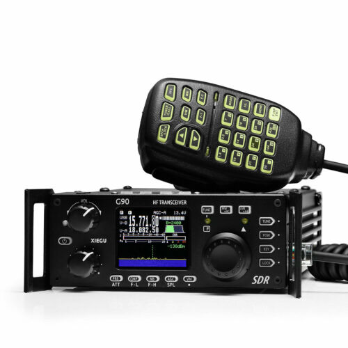
I decided that my Xiegu G90 DSP transceiver would be a good choice to fly with as it is compact and although it only puts out 20 watts, it should perform well at the higher altitudes found around the edge of Yosemite, even on SSB.
I packed the G90 in its original box, which not only provided protection for the rig with the Styrofoam inserts, but it also provided enough space to tuck in a mini un-un, some power cables, a copy of the manual, my mini log book, and a pencil.
I printed an official copy of my FCC license and included that as well in the G90 box and, using a Brother label maker, I labeled the outside of the box, “Property of Amateur Radio Station AB1DQ, Cheshire CT.” While based on the accounts of flying with ham gear that I read that others shared online, I didn’t anticipate much difficulty going through TSA with my shack-in-a-bag, but I felt a professional looking packing job might be useful if any TSA agent asked hard questions.
Originally I planned to power the rig from the rental car battery, I made two sets of power cables that terminated in PowerPole connectors that interfaced with the G90 power cord. One set had battery post clamps to attach directly to the car battery, and the other had a 12 volt cigar lighter plug. Based on the 8 amp rated current draw of the G90 at maximum 20 watt output, I felt I didn’t run much risk of blowing the 15 amp cigar lighter fuse, but I did pack extra fuses just in case.
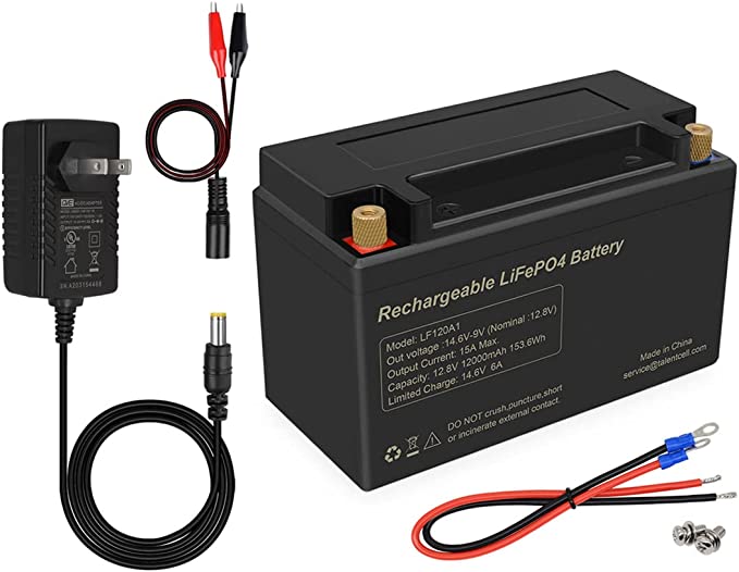
Then I decided for not much more space (but a bit more weight) in my go bag, I should bring a LiFEPO4 battery and charger which would allow me more flexibility to operate, should I want to, after we returned the rental car for the San Francisco portion of our trip.
I found a deep cycle 12Ah 12.8 battery on Amazon that met my specs for less than $60. I made a short jumper cable terminating in PowerPole connectors which I pre-attached to the battery. Like the rig, I kept the battery in its original packaging in my go-bag, again labeling the box with my callsign and contact information. The battery did catch the attention of the TSA agent, but after a careful visual inspection, she returned it to its box and handed it back to me.
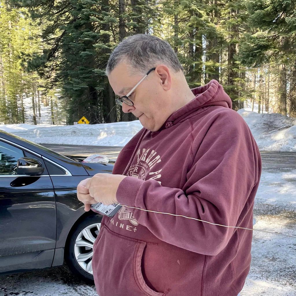
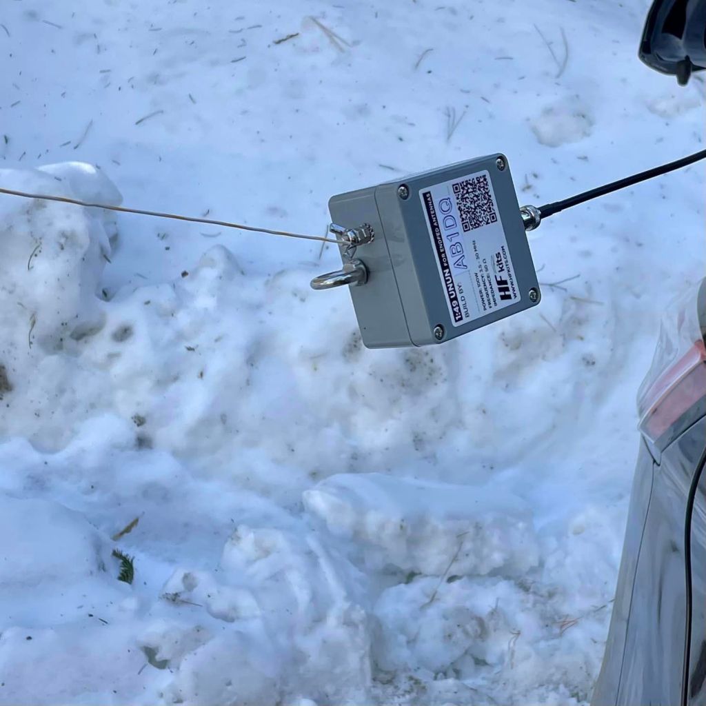
My antenna plan was to use an End Fed Half Wave. A couple of months back I built a pair of 49:1 un-uns from HFKits.com, and had yet to try them out on the air. This seemed like a great opportunity, so I packed both along with 60′ length of basic hookup wire to use as the radiating element.
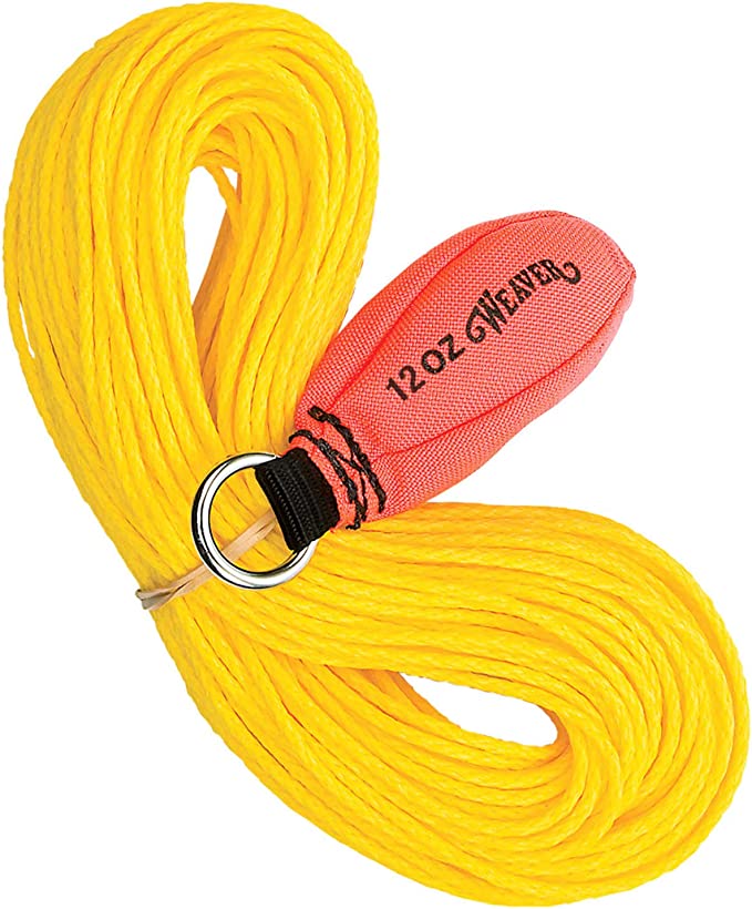
I have been one who has always struggled with launching lines into trees for my wire antennas, so after some YouTube research, I thought I’d try something new. – an arborist throw-line attached to a 12 oz weight. Given the altitude of the park’s rim from where I planned to operate, I didn’t need too much height for the antenna, The 20-30′ or so I could get the high end up in a sloping configuration should suffice, so the throw-line seemed like a promising option.
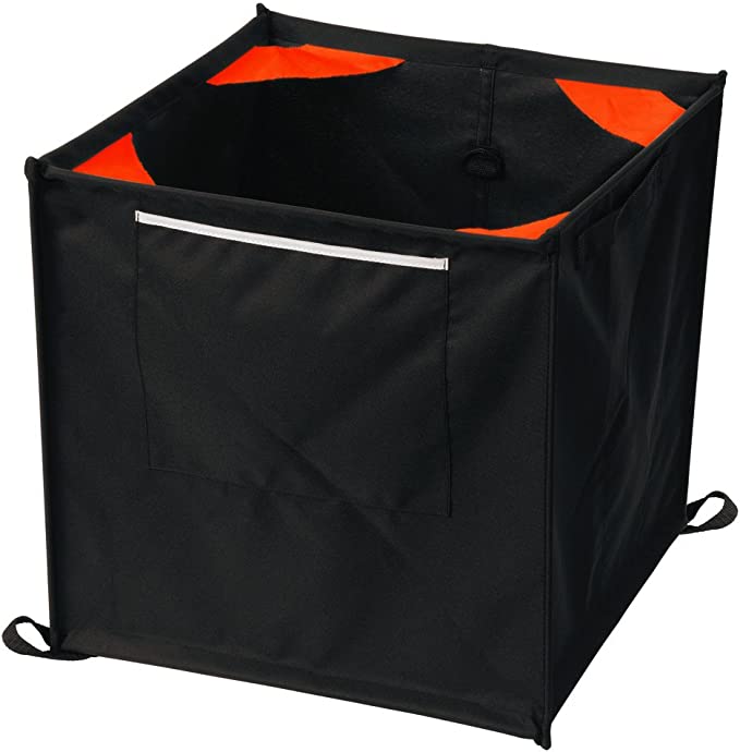
I found just the thing again on Amazon, and I also decided to add a collapsible throw line storage cube, which would allow me to keep the line untangled during transport and deployment. The cube was great because it folds flat but its 16″ square sides meant that it would not fit in my duffel bag go-kit, so the throw line and storage cube would have to be packed into my checked suitcase. The flatness of the collapsed cube made it easy to pack at the bottom of my checked full size suitcase along with my clothes for the trip.
I used a couple of gallon size Ziplock bags to pack the miscellaneous items I would need, including my Morse key, 60′ of antenna wire, additional pencils and a pencil sharpener, a couple of power cable extension cords, etc. All items, aside from the throw line and cube, fit nicely in a small duffel bag along with my laptop, a couple of books and a few other carry on items for the trip that would stow nicely in the overhead bin.
Aside from the visual inspection of my carry-on bag by TSA, with the careful attention given to the battery, I had no problems taking the go-kit through airport security and onto the plane. I wasn’t asked any specific or probing questions about the contents of my bag.
Operating Yosemite
We were staying at the Yosemite Valley Lodge while in the park, which we found to be great accommodations for our visit. However, being deep in the park valley, with rising mountains on all sides, it made sense to find a spot from which to operate that was higher up off the canyon floor. And, while I’m aware that a big part of the POTA program is to present ham radio in a positive light to the uninitiated, and as much as I love being that goodwill ambassador for our hobby, I tend to get nervous when I’m being watched, particularly when I’m not completely familiar with gear or a configuration I haven’t tried before. So I was also looking for an operating site that was a bit more remote with less foot traffic.
After studying a map of the park, I decided a good bet would be to drive west up Big Oak Flat Road towards Porcupine Flat which was north of us and had a picnic area. However, the Tioga Road is closed in the wintertime, so we ended up stopping near Toulumine Grove at the road closure.
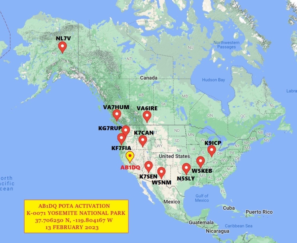
There was a convenient parking area there at 37-706250 N, -119804167 W which provided both altitude and minimal foot traffic. The spot looked ideal for my planned activity so I parked the rented Ford Edge and began my set up.
This was the first time I tried a throw-rope and I found the deployment to be about as easy as it seemed in the YouTube videos I had watched. However, due to some chronic shoulder pain I’ve been experiencing in my right arm, I have been lacking my usual range of motion and wasn’t able to get the bean bag weight over my chosen branch, but needed to settle for the next one below, which I estimated to be about 20′ up.
I detached the throw weight and connected the the end of my 60′ antenna wire to the rope and hoisted it up to the branch and tied the throw rope to the trunk of the tree. I asked my wife to stretch out the sloping antenna wire to the point where it met the ground and I repositioned the car.
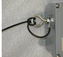
I attached the end of the antenna wire to the un-un and connected the un-un to the G90 via a 25′ length of RG58. The antenna was sturdy and up high enough that any passersby should not run into it, but I realized after the fact that I failed to make appropriate use of the strain relief on the un-un. (See right most photo below for how to do it right!)
While I should have taken the time before flying off on my trip to test and trim my wire element to obtain a minimal SWR, I didn’t have the opportunity to do so, but I was pleased that the G90’s auto tuner was able to obtain a 1.8:1 SWR.
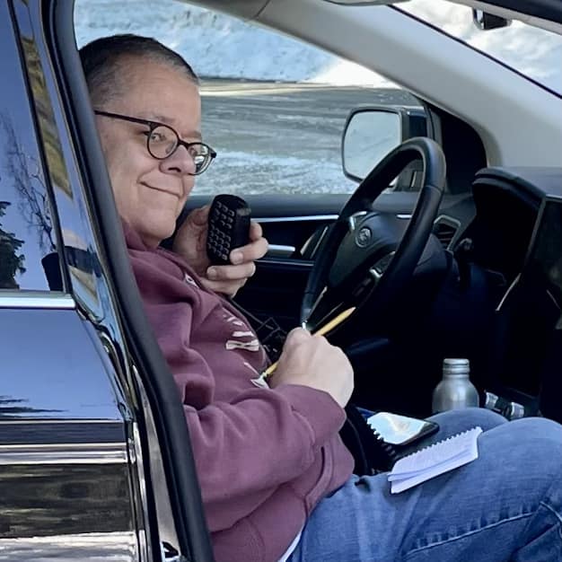
Initially I powered the G90 via the cigar lighter plug I fashioned, but found the voltage reading on the G90 panel to be right around 11.0 V. Upon switching to the LiFePO4 battery, the G90 was reading around 13.0 V. so I continued to use the battery.
The immediate advantage to operating (very) remotely and on a battery, is how quiet, nay, silent, the HF bands are. A far cry from the noise floor that is typical at my home QTH fixed station.
I began calling CQ POTA on SSB on 14.324 and over the hour I had available to operate that day, I made 11 contacts. Fewer than I had hoped for, but enough to make my activation successful.
With my 20 watts and a wire, I worked as far north as NL7V in Fairbanks AK who rated my signal 53, as far east as K9ICP in Greenwood IN who reported my signal 59, and as far south as W5NM in Las Cruces NM who provided a 55 report. Included in my 11 contacts was a single Park-to-Park contact with K7CAN who was activating Minidoka Internment National Historic Site, Park K-0849 in Idaho. We swapped 59 reports.
Lessons Learned & Conclusions
I mentioned due to our compressed travel schedule, I only had about an hour of operating time, but it didn’t matter as I had a great deal of fun. This was only my sixth activation in over two years, so I’m still very much green and learning.
The positive takeaways from this trip was I learned how to effectively and efficiently pack an HF go-bag for air travel, and while I will need more practice, I did successfully and quickly deploy my EFHW antenna with the arborist throw line.
Areas for personal improvement include the proper testing of new gear at home before traveling to a park. I shared that despite not testing my un-un and antenna prior to traveling, I had an adequate SWR once on site. (I did bring extra wire and a pair of nippers in the event my SWR was so far off I needed to do major mods on site.)
Finally despite the entire station fitting comfortably in my go-kit duffel bag as carry -on luggage, the bag was pretty heavy and given my shoulder pain I mentioned above, it was a bit uncomfortable to lug through the airport and stow in the overhead bin. Thus, I splurged and stopped at a UPS store to have the radio and battery shipped home to me so I didn’t have to fuss with the weight or the TSA on the trip home. That ran me about $60 for packing and shipping, but the gear did arrive home safely.
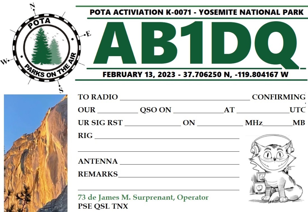
Finally, I’m planning on issuing QSLs to all stations I worked during my POTA activation. I still love collecting cards and am one of those old-school hams who hangs wallpaper. I had sent out cards for some of my previous activations, primarily to ops who indicated they were welcoming of receiving cards and would reciprocate.
I’ve designed a commemorative card for my Yosemite activation and will be printing the cards at home on card stock.
My ham resolution for 2023 is to get on the air much more than I have in recent years and I’m planning on making POTA activations a major part of that goal. The Yosemite trip was a great, albeit limited experience, that helped me build confidence and comfort.
What suggestions, thoughts or ideas do you have to share that I and others may use as we take to the parks with our rigs? Do you have a memorable POTA experience to share? Feel free to add a comment or contact me directly by email at james@ab1dq.com.
73 & thanks for reading! James
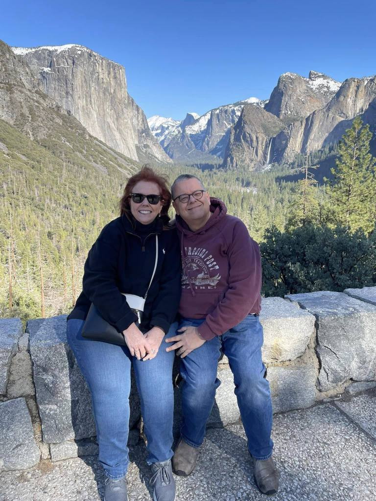
AB1DQ, James & XYL Ellen, at the Tunnel View Scenic Overlook in Yosemite National Park, February 2023. This photograph was taken by a charming young Ukrainian woman we met at the overlook. She shared some of her story of the affect the Russian invasion has had on her and her family and we had the opportunity to express our heartbreak and our support for her people.
OLYMPUS DIGITAL PEN EP-3 edited with iPhone Hipstamatic app.
I passed through my hometown of Lawrence, Massachusetts this past Sunday afternoon, returning home to Connecticut after a weekend visit with family and friends at Hampton Beach.
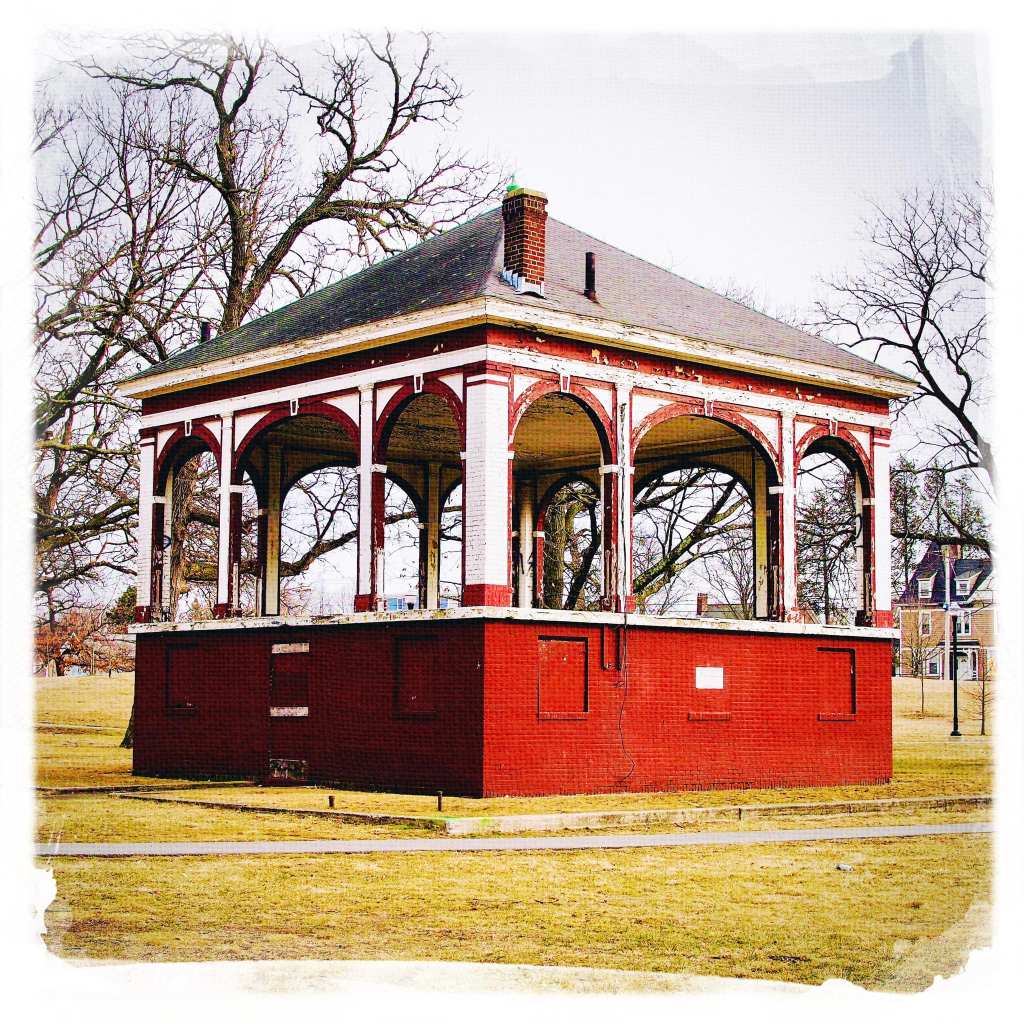
I strolled through the O’Connell South Common which, located two blocks down the street from the Market Street three-decker I grew up in, held many childhood memories such as feeding the squirrels with my grandfather, smoking Lark cigarettes filched from my grandmother’s pack with my friend Georgie under the slide, and sledding down the hill on chilly winter days with my sister and dad. So many memories.
I remember on a long ago Saturday afternoon, using the bathroom under the bandstand where I encountered a custodian watching wrestling (or perhaps it was candlepin bowling?) on a B&W TV in his small office in the Men’s Room. He seemed quite content passing the time in his subterranean porcelain fiefdom.
Can you ever go home again? I think if we’ve held on tight to the small and seemingly insignificant memories, perhaps we never left?
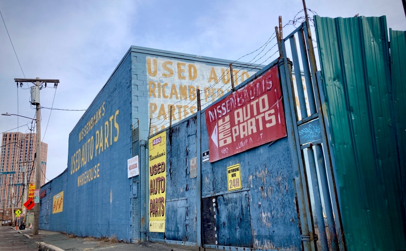
According to the company website, Nissenbaum Auto Parts was founded in 1910, by Jacob Nissenbaum, a Jewish immigrant who fled the repressions of czarist Russia, drove a horse and buggy as he collected rags and paper in Somerville and Cambridge.
Over the decades, future generations of Nissenbaums joined the business, in 1929, Joseph, Jacob’s son replaced the horse and carts with trucks and grew the business by purchasing scrap cars.
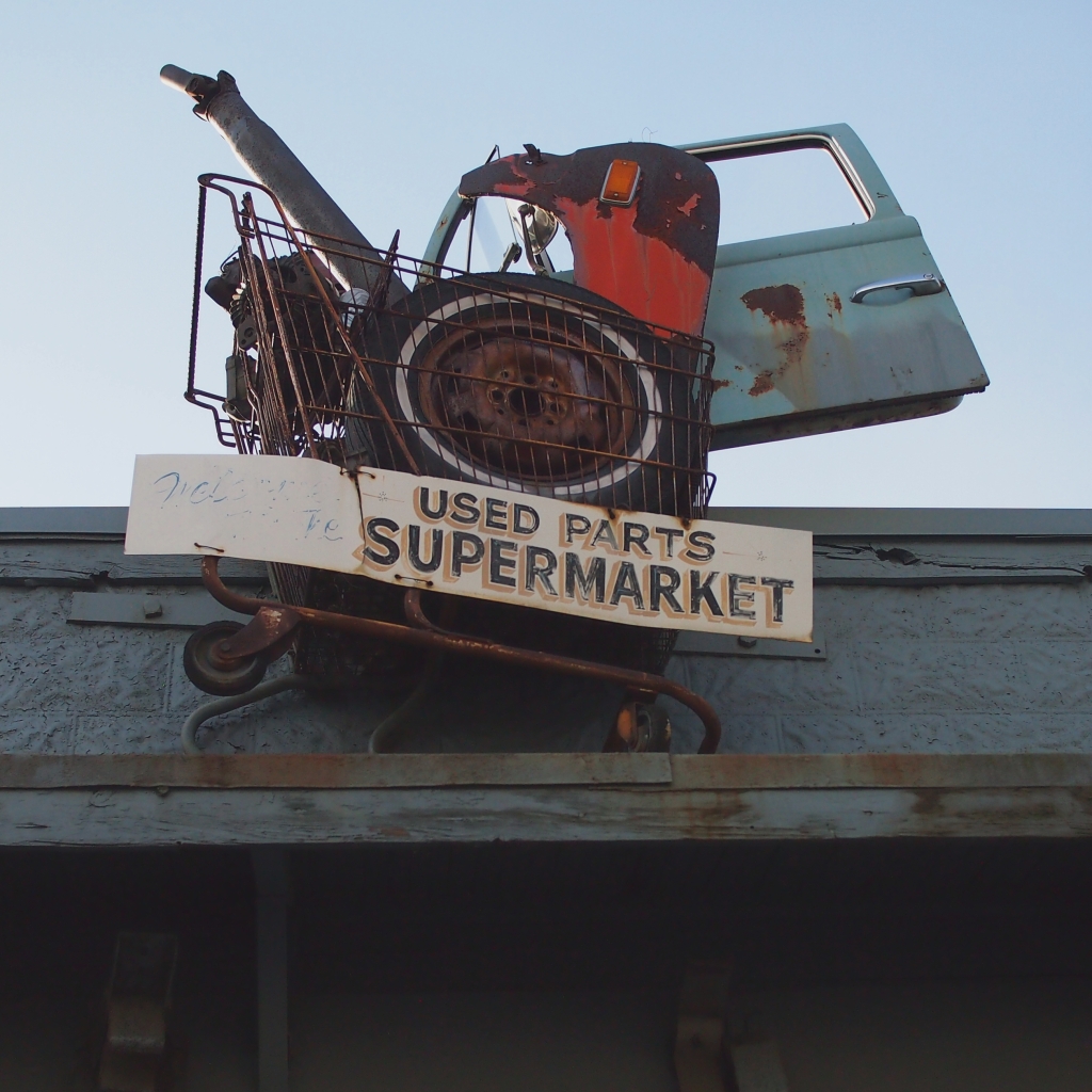
In 1937, Jacob retired, and Joseph passed away, leaving his son Max to take over as owner and manager who expanded the property and by the mid 50s, Nissenbaum’s started selling auto and truck parts, allowing customers to remove their own parts from the scrapped cars. The first state approved auto body incinerator was erected in 1964 and used until 1967, when vehicles were brought to the shredder.
The fourth generation recyclers, Joseph and Allen, joined the business in the mid 1960s and since that time, Nissembaum’s has dealt primarily in older automobile salvage. Today Neil Nissenbaum marks the fifth generation of family ownership, working alongside his father Joseph, who was 83-years-old in 2022 and his 78-year-old uncle, Allen
The property is now scheduled to be part of the Boynton Yards project, which opened a nine-story building nearby in May 2022, the first of four buildings planned for the life sciences.
According to the Boston Globe, the family listed the property for sale in December 2020, after discussions and years of watching how the neighborhood might change. The time felt right, the Nissenbaums reported.
Another factor, they said, is that demand for car parts has fallen off, particularly in a longtime blue-collar city that has seen more and more gentrification.
Not many years ago, Allen said, “everyone in Somerville had a used car. Who lives here now? People who ride a bicycle and drink latte. None of that group needs us.”
The Nissenbaums know their family history well, and they relate it with pride. They’re also realists, and they figure that the business will fade from most people’s memories after the new Somerville rises there.
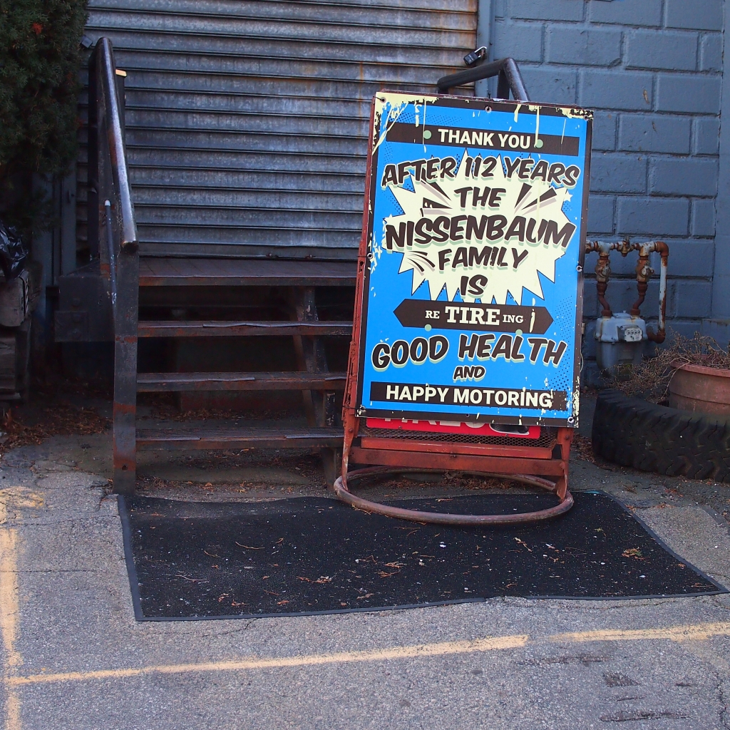
“The name has been out front for 112 years. But when people drive down the street in five years, they won’t know we were here,” Allen said.
I shot these photographs on a Sunday morning in February 2023 with fellow photographers, Dave Brigham and Mike Zeis. Dave, Mike and I are holding tight to the remnants of the 20th century world we grew up in. We share an enthusiasm for fading architecture of the 20th century and a love for hand-painted signage and urban blight and our visit to Nissenbaum’s did not disappoint.
The above photographs were made with my Olympus PEN EP-2 digital camera. Please feel free to leave your comments or share your memories of a fading Somerville as gentrification continues to re-invent the city.
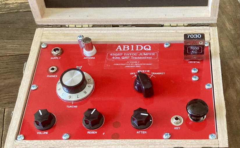
I was thrilled to see that the good folks at the Four State QRP Group released the 4th revision of their popular Bayou Jumper 40M CW Transceiver designed by Jim Giammanco N51B and David Cripe NM0S last year.
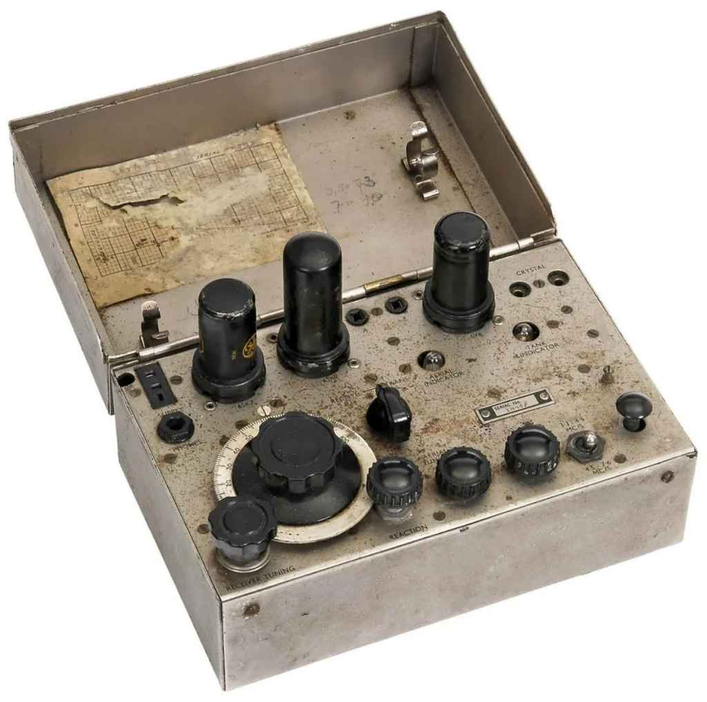
The Bayou Jumper, first released in 2017, is a 40M QRP transceiver that is an homage to the classic Paraset, the legendary transmitter/receiver supplied to the resistance groups in France, Belgium and the Netherlands during World War II.
Whaddon Mk VII – Paraset Clandestine Transceiver c. 1942
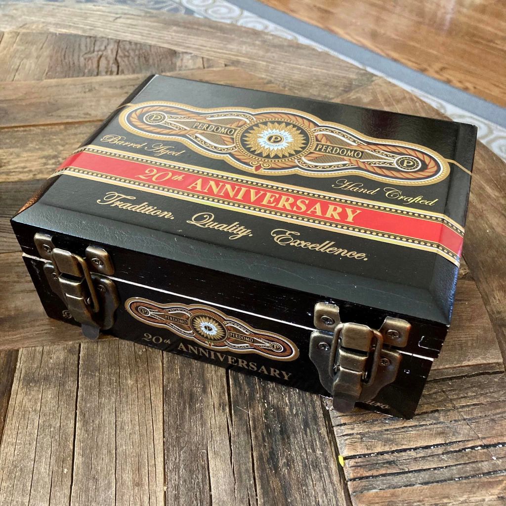
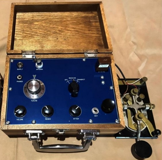
The Bayou Jumper, an updated solid state CW only radio kit is intended to be fitted into a hinged wooden suitcase style box available from Hobby Lobby or any other similarly sized box.
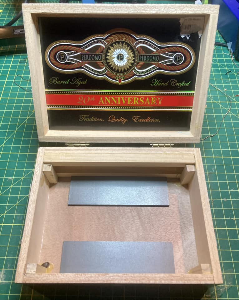
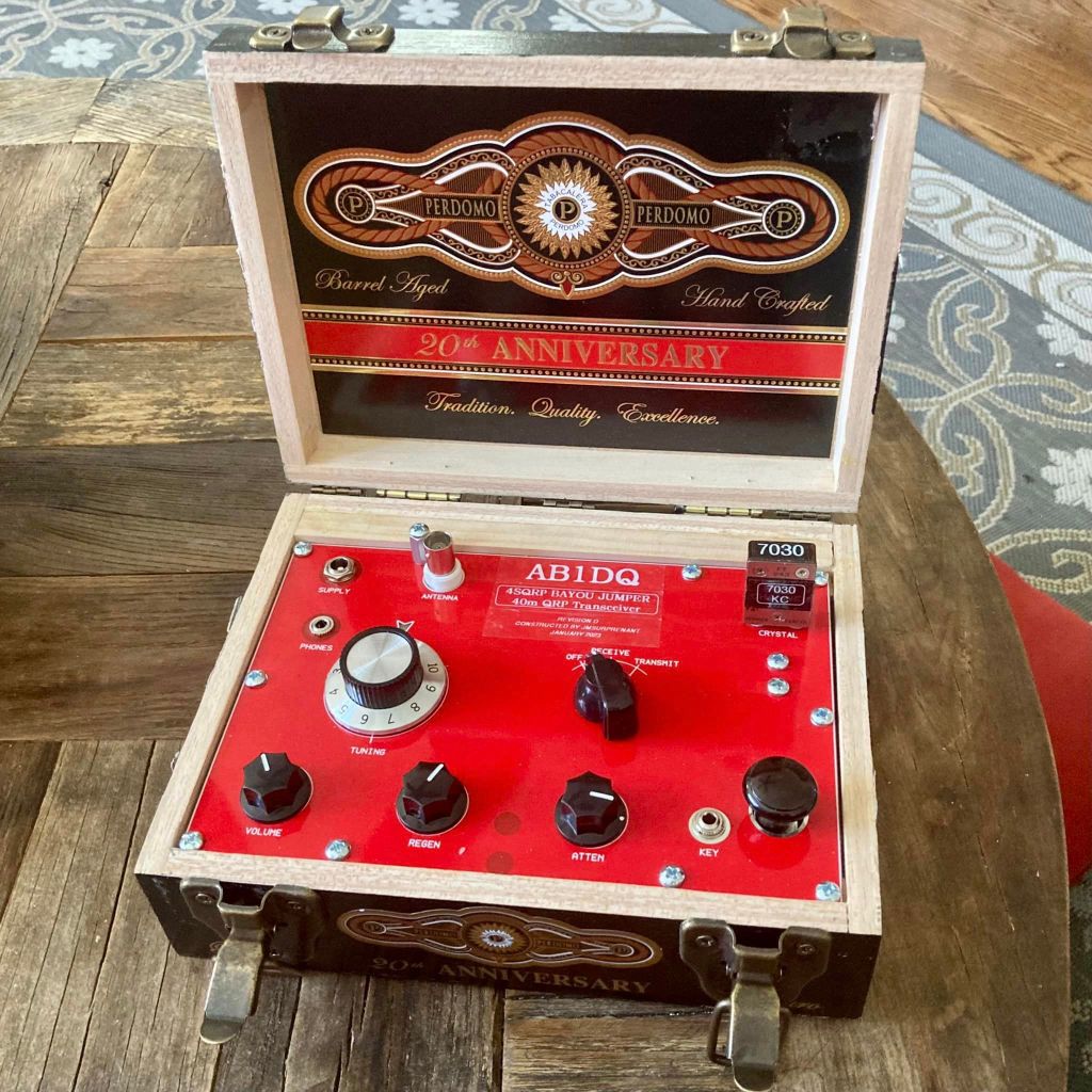
Given my recent obsession with building QRP radios and accessories into empty cigar boxes, I felt the Bayou Jumper would make an excellent candidate for cigar box treatment. I found a gorgeous Perdomo 20th Anniversary cigar box in my stash that was approximately the right size, featured gorgeous red and gold artwork on a black background and was constructed of heavier wood than many of the other cigar boxes in my collection.
The Bayou Jumper front panel was a perfect flush fit left to right in the Perdomo box, and only fell 1/2″ short front to back. I modified the box by gluing a 1/2″ square dowel along the top hinged edge to fill the empty space.
Other mods I made to the cigar box included:
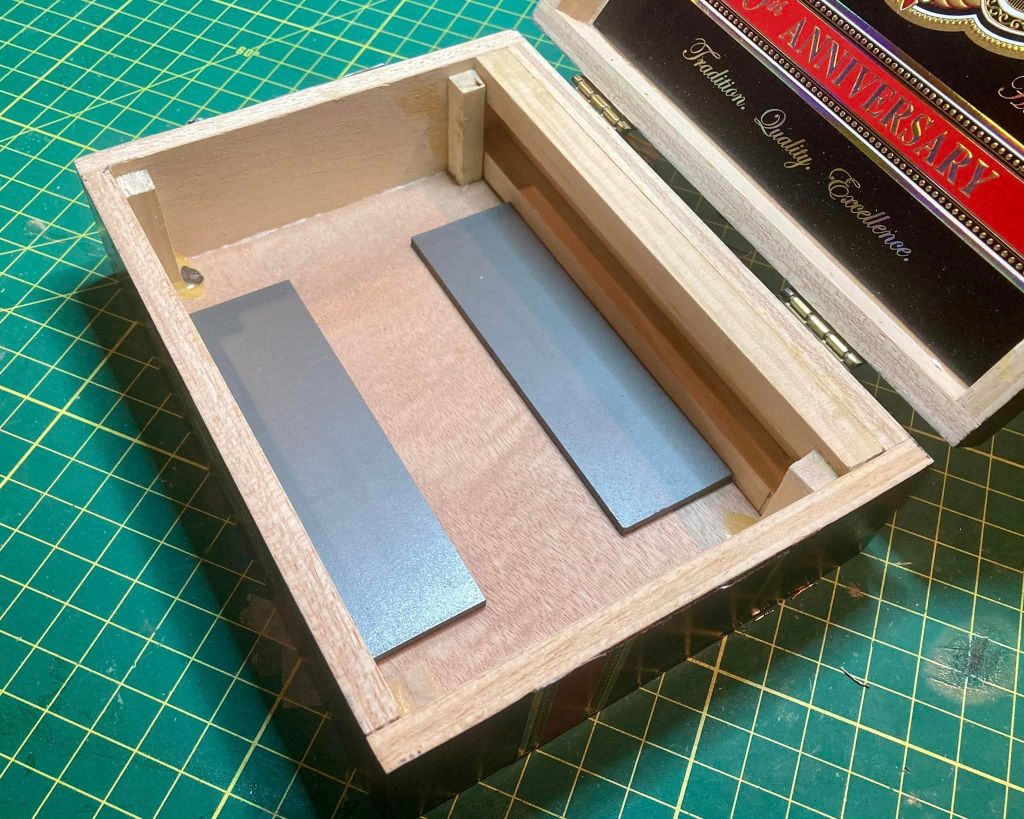
Adding weights to the bottom of the box to prevent the radio from tipping over backward when the lid was up and to provide a little more heft,
Adding a pair of latches to be able to secure the lid closed, and,
Reinforcing the original pressed in hinges with three supplemental screw-in hinges.
Building the Kit
I chose the Bayou Jumper to be my 2022 Christmas project. Professionally I have worked in an administrative role in higher ed for the past two decades and one of the biggest perks of working at most leading universities is they completely shut down for an extended winter recess. Building an electronic kit during my winter recess takes me back to my teenage years when I’d spend my holiday break from school constructing the electronic kits I received as Christmas gifts.
Like every NM05 designed 4SQRP kit I have previously built (the Murania One Transistors Boy’s Radio, the 4S-QRP Antenna Tuner, and the Ozark Patrol Regen Shortwave Receiver), assembly was a relaxing no-stress experience. Once again, I was very pleased with the high quality of the double sided etched-through printed circuit board, the quality of the electronic components and hardware, and the in-depth and easy-to-understand instructions and documentation.
I encountered only two minor issues in building the Bayou Jumper Revision D that were hardly a problem, barely an inconvenience.
The first was a missing resistor, R15, a 1/4 watt 100K ohm resistor. I have never experienced a missing part when building a 4SQRP kit and it’s probably just as likely I dropped or lost the resistor than it was wasn’t shipped in the kit. Regardless, I had the correct value resistor on hand in my home stock supply.
The second matter involved the jumper wires provided to supply current to the multi-color LED on the front panel from the main PCB. The instructions stated the kit included a 12″ jumper wire with header pins included in the kit that needed to be cut in half to make two jumpers. However, the jumper wire included in my kit was only 5.5″ long and once cut it in half as the instructions directed, one of the resulting leads was too short to mate to the header pin on the PCB.
As with the missing resistor, I had plenty of jumper wires that I use for breadboard prototyping on hand and was able to create the necessary jumper wires with sufficient slack to reach the contact points.
All in all, the kit went together in just 3 days’ time as I prefer to work slowly and methodically whenever I build a kit. (Whenever I rush through a project I typically find that any time I saved working quickly would be lost in extensive time consuming trouble-shooting that would be needed!)
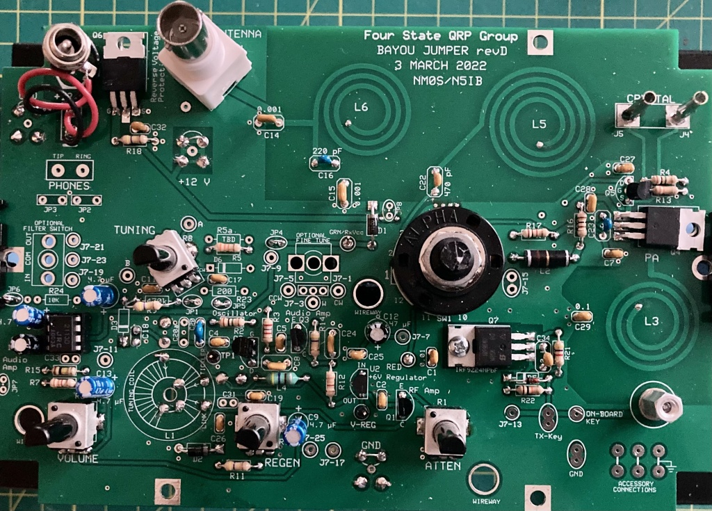
The topside of my populated PCB. Assembling the kit was straightforward and fun.
Winding the Transformer
The Bayou Jumper features three inductors etched into the PCB but still requires the winding of a single transformer on a T 6-7 toroid core. I have never found winding coils to be difficult or stressful, and in fact, I generally enjoy it especially when the kitter provides excellent directions and illustrations, which 4SQRP did.
The transformer required 3 windings, one of 19 turns, one of 4, and the last of 2. The completed transformer can be soldered to either the top or bottom side of the PCB, based on the builder’s preference and tje screen printing on the circuit board makes installing the completed transformer essentially foolproof. I chose to mount the transformer to the bottom side of the board to make it easily accessible for adjusting the spacing of the winding to adjust the receiver’s tuning range.
The completed transformer mounted to the bottom side of the PCB.
Faux Crystals?
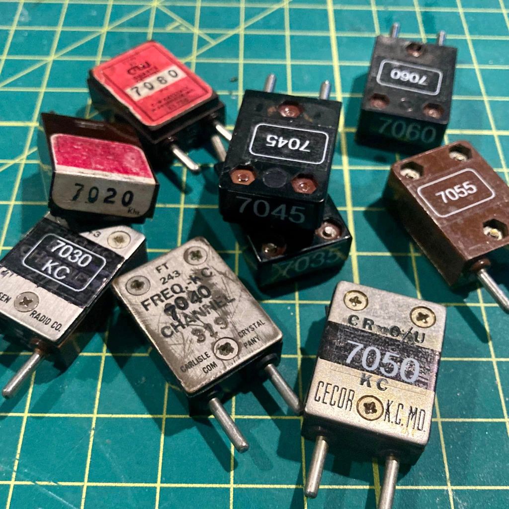
The Bayou Jumper’s crystal socket accepts the classic FT-243 crystal form, a popular Cold War era crystal size that today is no longer manufactured and increasingly rare.
The Bayou Jumper comes supplied with a pair of HC-49 crystals for 7.030 and 7.122 MHz, and two crystal adapter boards to fit the HC-49 crystals into the FT-243 sockets.
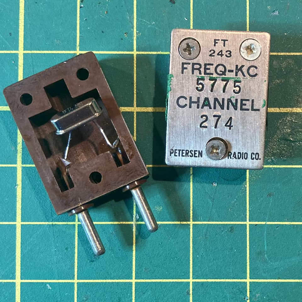
Vintage FT-243 cases are large enough to accommodate modern small HC-49 crystals and with its 3 screws, the FT-243 can be easily opened and re-sealed, making it possible to re-stuff FT-243 cases for modern QRP use.
Using several of the FT-243 crystals for non-amateur frequencies that I picked up at ham-fests, I have modified 9 crystals for use on the 40 meter CW sub band, all ready to go in my Bayou Jumper.
Receiver Alignment and Final Assembly
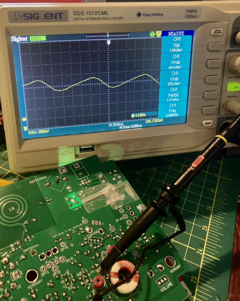
Again, the excellent directions made aligning the receiver a snap. Instructions are provided for a variety of alignment methods using an oscilloscope, a frequency generator or a calibrated receiver capable of CW reception. Having all three available to me, I tried all three methods and was pleased when all three were in sync.
I started taking a frequency reading with the tuning dial set to the low end of the scale with my O-scope and read 6.897 MHz.
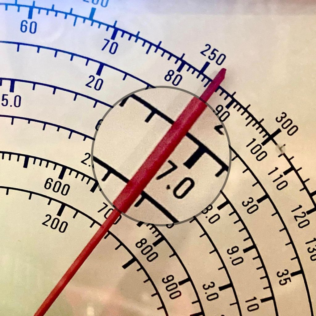
Next I tried sweeping the dial of my frequency counter to spot the point where oscillation could be heard in the earphones. My frequency counter has an analogue scale and was able to read the resonant frequency at about 6.9 MHz.
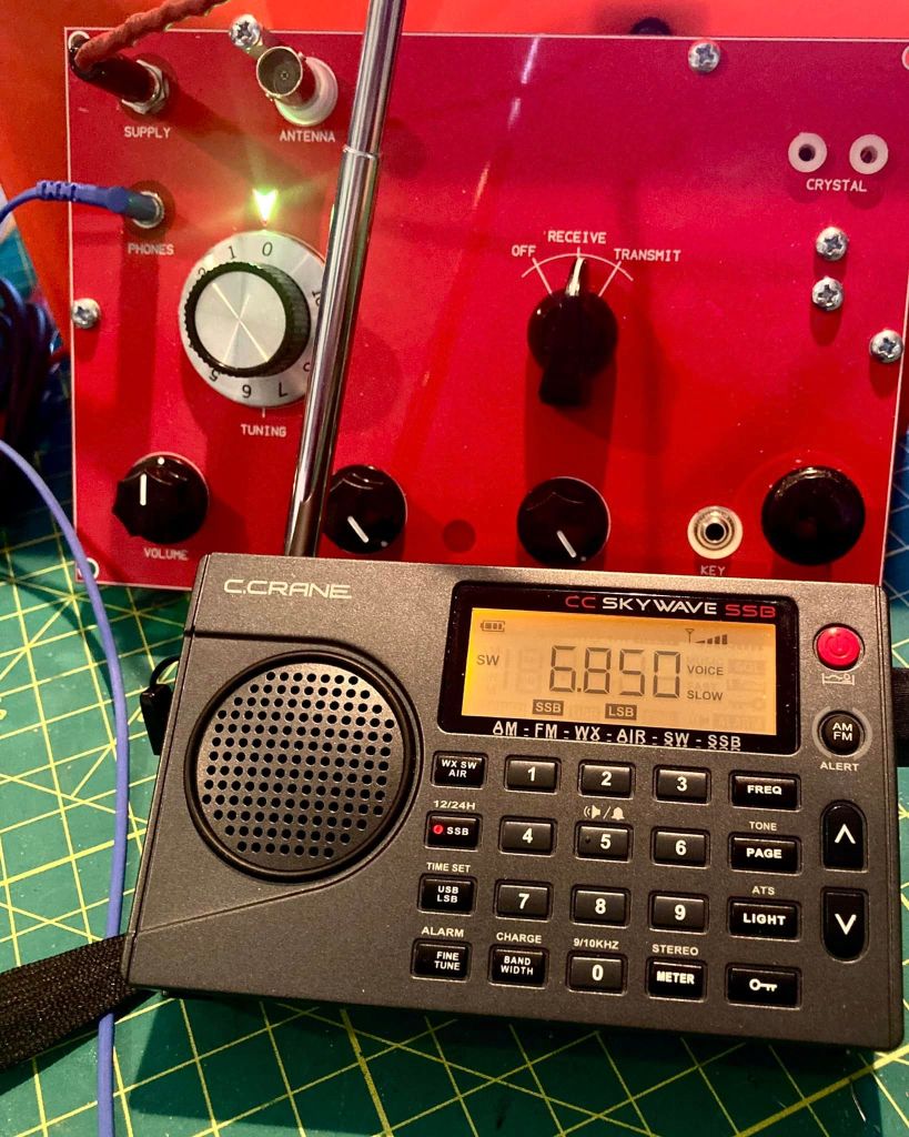
Finally I set my portable C. Crane Skywave SSB travel radio for LSB and tuned to the 6.900 and tuning up and down was able to hear the receiver’s oscillator at about 6.895 MHz.
Following the directions to adjust the tuning range by spacing the L1 windings on the transformer closer together or further apart and then adjusting the C30 trimmer, I was able to achieve a final tuning range of 7.000 – 7.167 MHz which should be more than adequate for the CW sub-band I would use.
Finally, I followed the directions to verify regeneration and was happy to find that my receiver needed no further adjustment. Satisfied with my work, I mounted the radio in the cigar box and am looking forward to putting my Bayou Jumper on the air.
Stay tuned for Part II where I will report on my experience operating the Bayou Jumper on the air and any future adjustments or modifications.
My second HecKits build was a great experience – just like my first!
I have become a big fan of the HecKits QRP kit line. A few months back, while looking for a modern dip meter kit, I discovered HecKits and ordered their FET Dip Meter. My experience was with that first kit was great in every way. I was impressed by the high quality of the materials and components, the easy to follow directions, the excellent documentation, and the outstanding customer support courtesy of Darrel Heckendorf, the man behind HecKits.
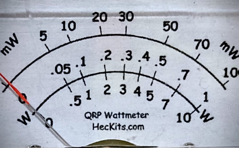
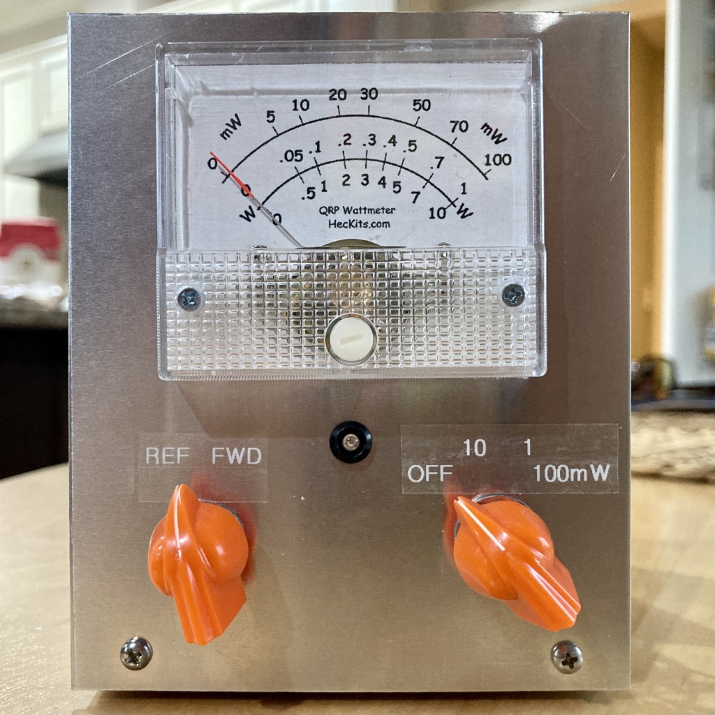
My wife gifted me the HecKits QRP mW meter as a birthday gift this year and I had the time this past weekend to tackle the project.
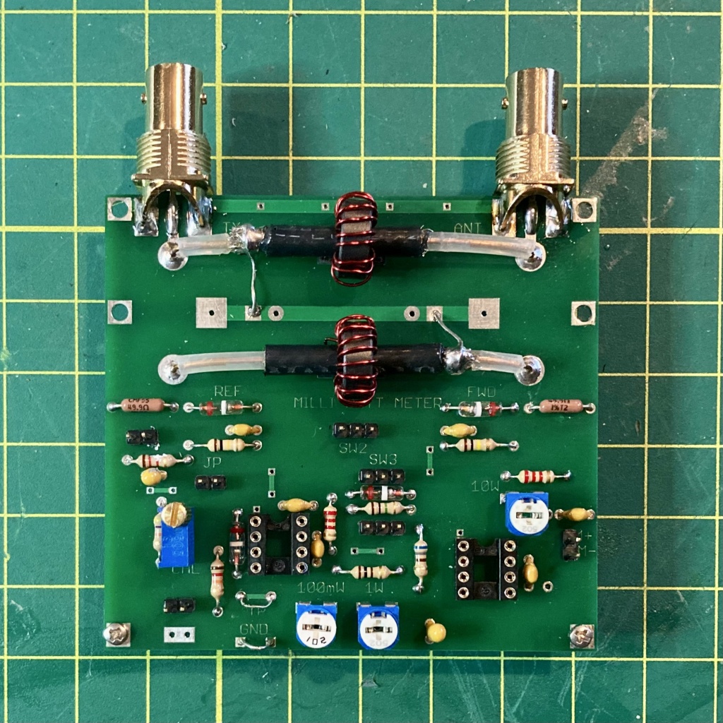
Once again, HecKits gets the highest marks for its documentation. The construction manual, sent by PDF by Darrel, was comprehensive, easy to follow and full of detailed illustrations. And again, I was very impressed with the high quality of the parts and materials included in the kit. Everything needed to complete the project is included and the fit and finish is unparalleled.
I was very impressed with the screen printed plated through PCB and included in the kit is a handsome precision drilled metal enclosure giving the finished project a professional appearance. While building the meter, I frequently paused to appreciate the high attention to detail that was put into the kit. For example, the manner in which the BNC connectors mate with the PCB and back panel of the enclosure shows precision engineering that went into developing the kit.
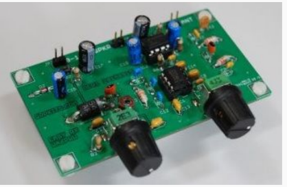
The completed circuit board. It came together in just a couple hours’ time and I was very impressed with the high quality and attention to detail that went into engineering this kit.
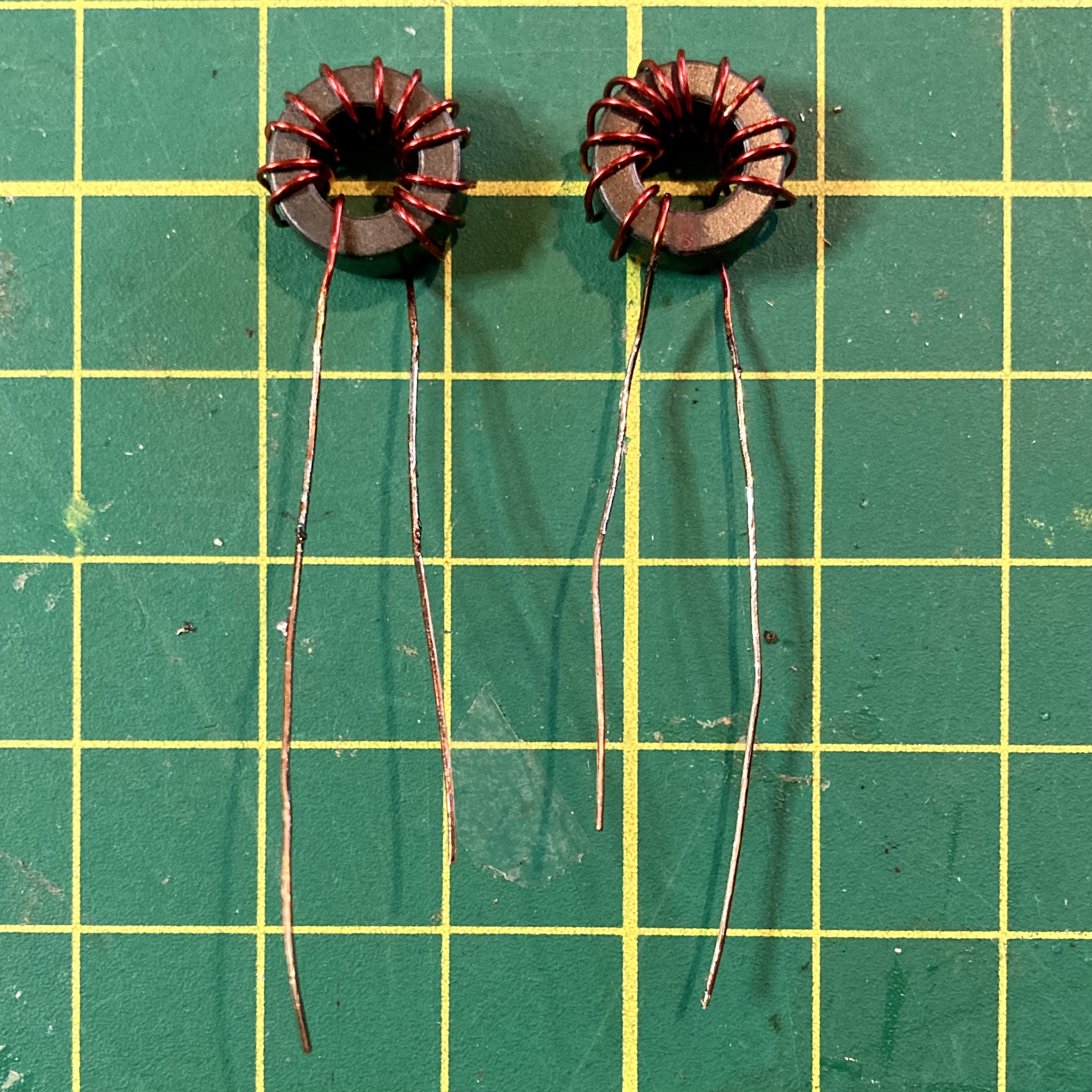
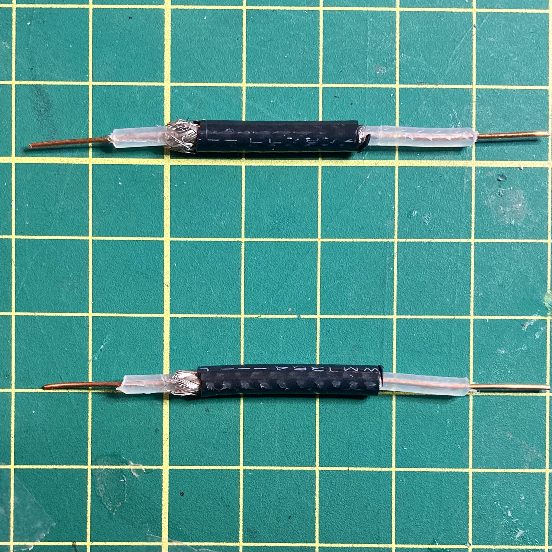
I was able to assemble the kit from start to finish in about three hours’ time – and I do work slowly and try to be meticulous in my work. The meter requires the builder to wind two toroids – a task that I never mind – and again the detailed directions would make it nearly impossible for even a novice builder to fail.
I did run into a small glitch, however. When I finished assembling the kit and began the calibration process, I was disappointed to find that the meter was not responding when I first applied power.
I removed the PCB from the chassis to begin troubleshooting. I had assumed perhaps I messed up the polarity on a diode or tantalum capacitor, but quickly discovered the problem was the ham-fisted way I inserted one of the ICs into the DIP socket, smooshing one side of the pins against the socket. I carefully straightened the pins, reinserted the chip and VOILA! All was well.
HecKits gets big props for the calibration process too. All that is required is a precision voltmeter and an RF tuning tool or eyeglass screwdriver. The kit has a multi-turn pot on the PCB that is used to adjust input voltage for calibration purposes. Once the builder sets the input voltage to the specification, the meter is adjusted for full deflection at 10 watts, 1 watt and 100 milliwatts by adjusting the corresponding trimmer pot on the PCB. What a snap!
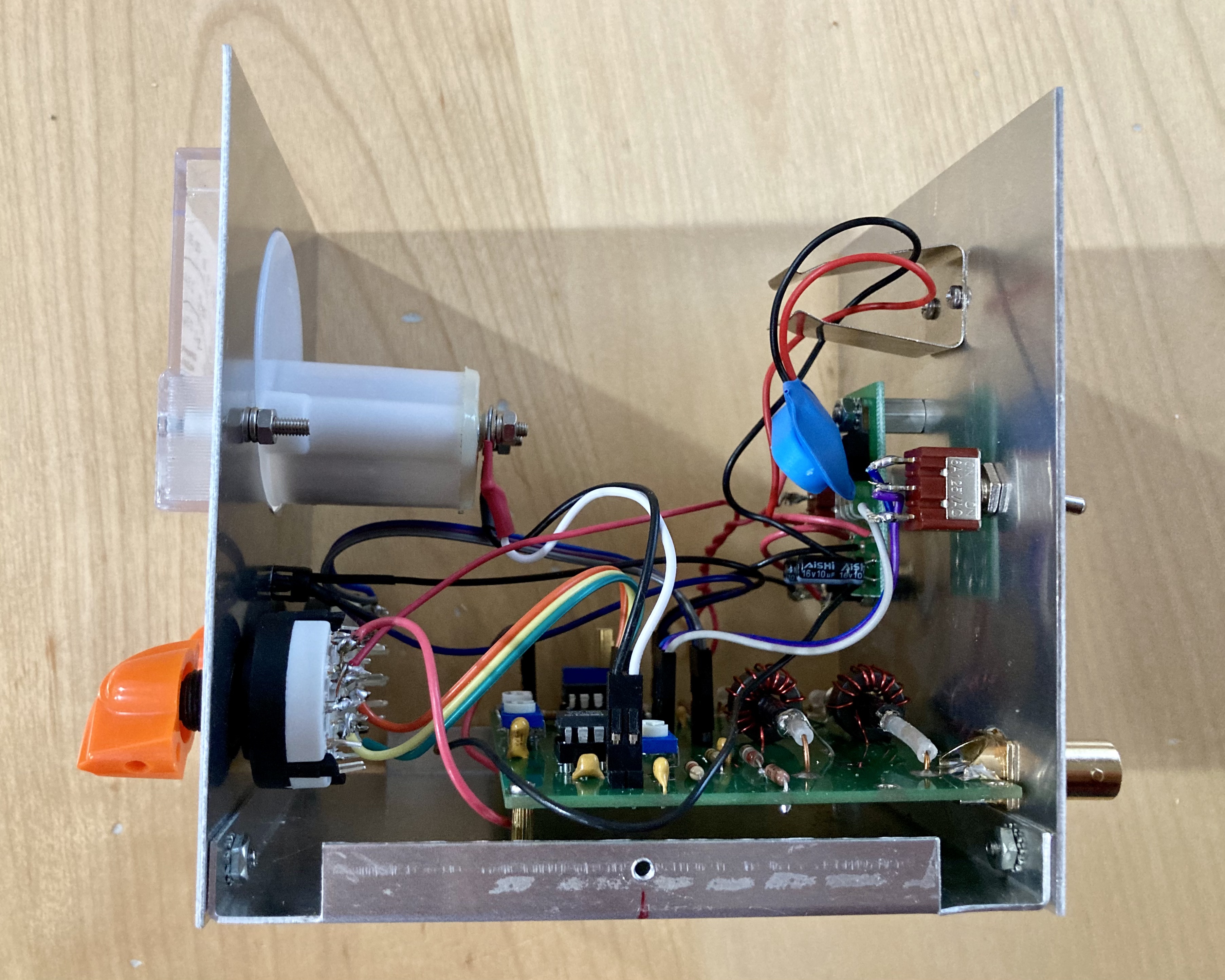
My finished meter – I swapped out the original black knobs for the mini orange chicken-heads…. I do stuff like that – kind of makes my gear unique.
I’m eager to add my new wattmeter to my QRP station and I look forward to my next HecKits build. You can get your own HecKits QRP meter or one of their other fine kits on their website – https://heckits.com/shop-heckits. I highly recommend their products for anyone who enjoys building their own QRP gear.
Have you built a HecKits kit? What was your experience? Please leave a comment or drop me a line at james@ab1dq.com.
Thanks for taking the time to visit my blog! 72 de AB1DQ / James
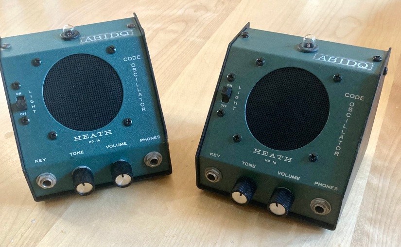
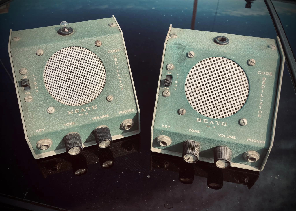
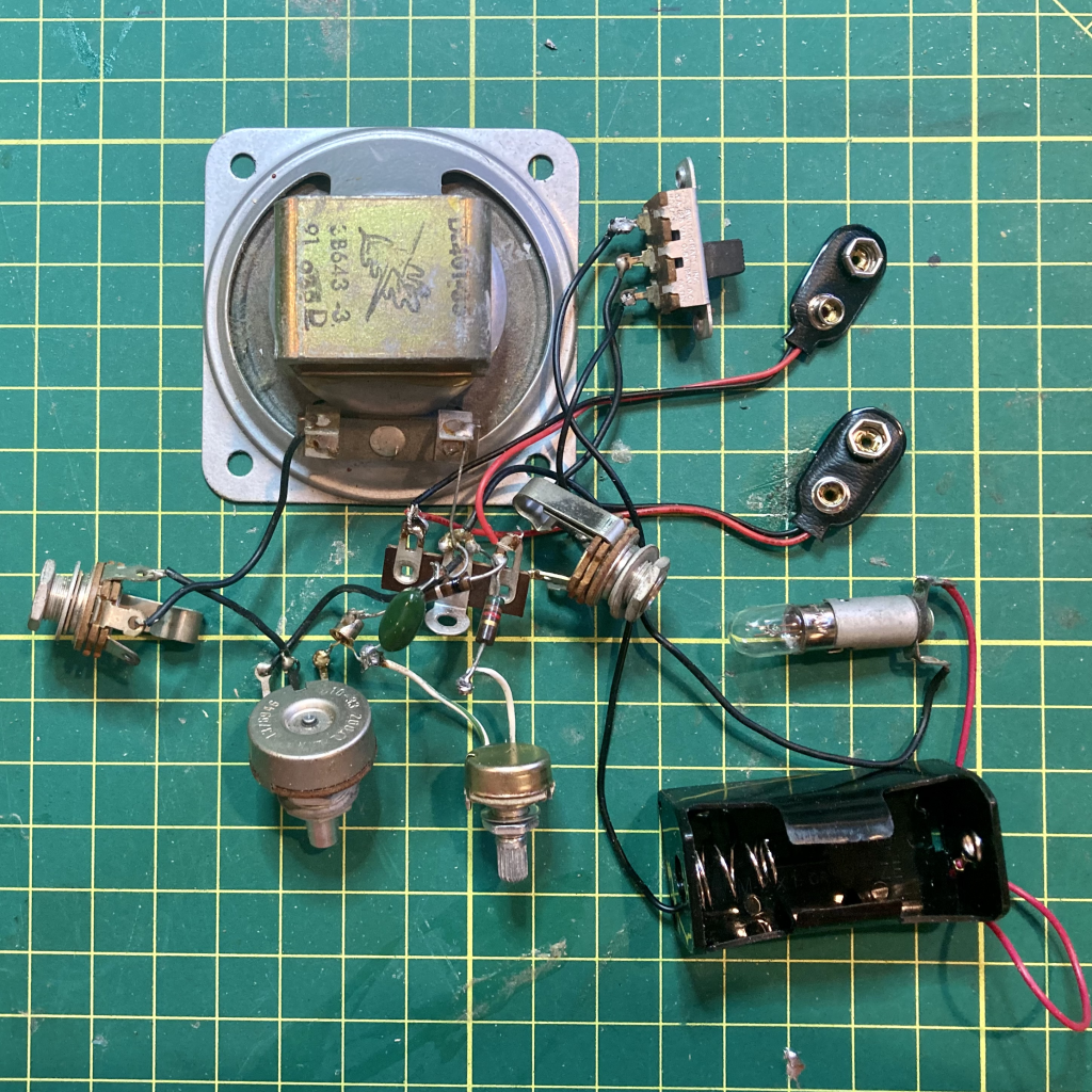
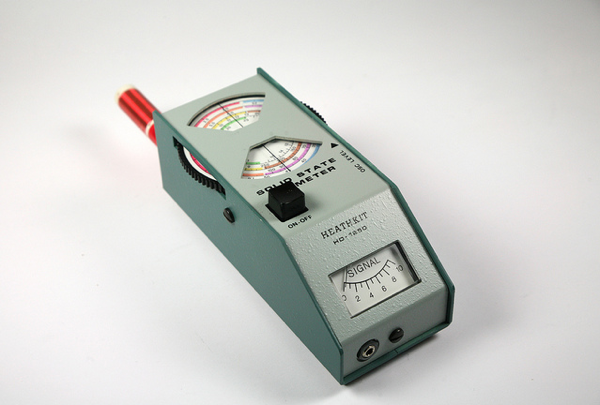
This August I picked up a pair of Heathkit HD-16 Code Practice Oscillators for $10 at the flea market at the ARRL New England HamXposition in Marlboro, Massachusetts. The CPOs were tech-specials, non-functional, but ‘mostly there’ with only a few missing parts.
BEFORE: What $10 will buy you at a ham radio flea market.
The HD-16 was Heathkit’s second code practice oscillator, introduced in 1974 and following the first Heath CPO, the CO-1 which was first sold in 1959. The HD-16 was sold until 1974, replaced by the HD-1416 in 1975 which sold with a few cosmetic variations until 1990.
Up until the turn of the century, prospective hams needed to demonstrate the ability to copy and send Morse Code at 5 words per minute (WPM) along with passing the written practical exam to earn the entry level Novice Class license. Advancing to higher class license classes required the upgrading ham to demonstrate the ability to send and receive code at faster speeds – 13 WPM for the General license and 20 WPM for the Amateur Extra Class.
In 1999 the FCC eliminated the 13 and 20 WPM upgrade exam requirements requiring hams to only demonstrate an ability to send and receive code at 5 WPM for high frequency privileges. Then, in 2006, the FCC eliminated all Morse Code testing altogether in accordance with the worldwide policy change the International Telecommunication Union made in 2003,authorizing each member country to determine whether or not to require individuals to demonstrate Morse code proficiency for licensing.
Despite the fact that hams no longer have to demonstrate the ability to copy and send Morse Code, operating CW or Continuous Wave with code remains as popular as ever in amateur radio. Many hams today choose to learn the code and many of us (yours truly included – a ham who only needed to pass a 5 WPM exam back in 2002), very much enjoy ‘pounding brass.’
Thus, the code practice oscillator, or CPO for short, was and remains a very useful piece of equipment for any ham aspiring ham to operate using Morse Code.
My Restoration Project
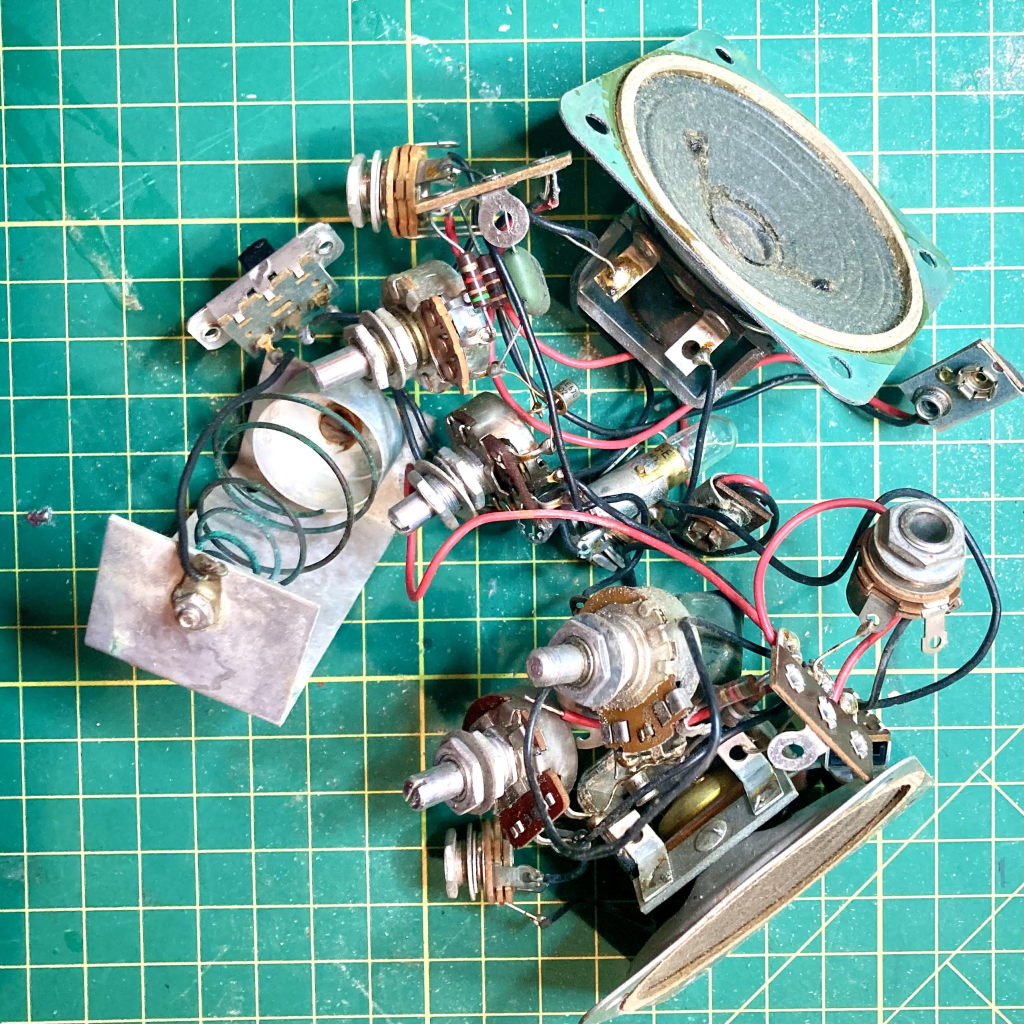
I began by disassembling both units completely and saving the screws, nuts and other hardware in (what else?) a cigar box in order not to lose any original parts.
The guts of both CPOs liberated from their cabinets.
I washed the cabinet parts in warm water and dish soap and gently scrubbed away at the stains with a soft brush. The back halves of both cabinets were scuffed and scratched badly so I chose to re-paint them in flat black.
Purists would only use the signature Heathkit dark green paint, but I didn’t have any on hand and, while I appreciate complete restorations of antiques, my philosophy for repairing old radio gear has always been to take advantage of what is available to make the vintage equipment usable to me today.
After sanding the enclosure backs with a fine grit sandpaper I applied 3 thin coats of flat black paint and then coated all pieces with 2 coats of clear coat. To compliment the blacked out cabinet sides, I also painted the speaker grilles with flat black paint and replaced the enclosure screws with new black screws.
On to the electronics
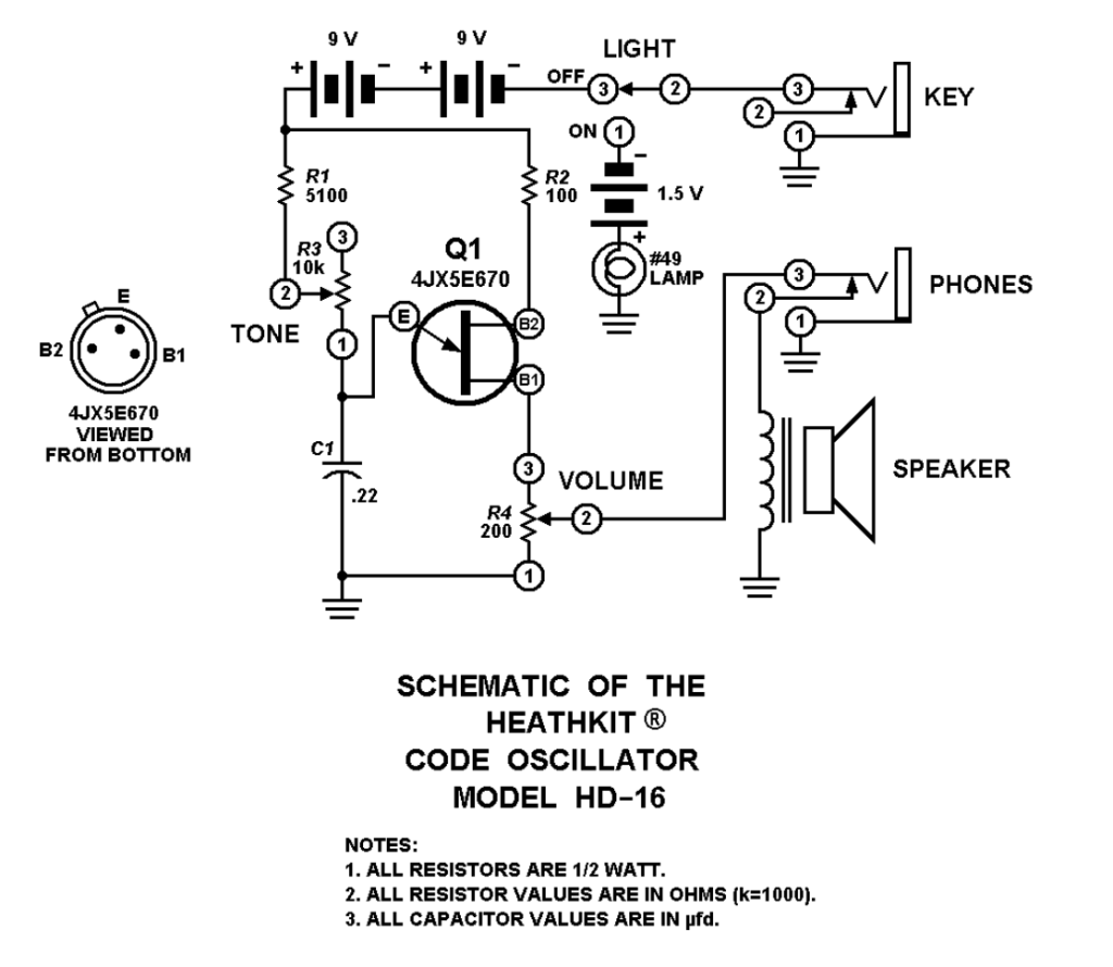
I found the original HD-16 manual online and printed a copy for reference. Like all Heathkit manuals, the HD-16’s was well written and included the schematic, complete specs, and some nice content on circuit theory and Morse Code.
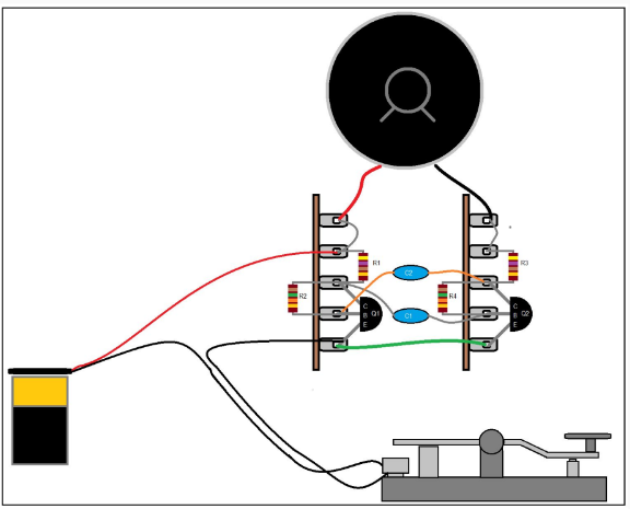
Heahtkit HD-16 schematic from the original manual.
Circuit theory
From the original Heath manual…
The unijunction transistor, Q1, is a special type of semi-conductor device, with two bases and one emitter, which acts as a relaxation oscillator in the following manner: When the key is closed, capacitor C2 is charged by the battery voltage through resistor R1 and the Tone control until the Emitter (E) voltage reaches the point at which the Emitter is forward biased with respect to B2.
Emitter current then flows because the dynamic resistance between the the Emitter and base one (B1) then drops to a low value. R2 drops the battery voltage to a low level, permitting C1 to charge to a higher voltage than B2.
Capacitor C1 discharges through the Emitter and Volume control until the voltage at the Emitter drops to the point where the Emitter is no longer biased. The cycle then repeats itself at a rate governed by the setting of the Tone control.
The pulsating base current, or oscillator signal, is developed across the Volume control. From the arm of the Volume control, the signal is coupled through the normally closed contacts of the phones jack to the speaker.
The lamp circuit uses the key as a switch that makes and breaks the C cell battery voltage to the lamp.
On Unijunction Transistors
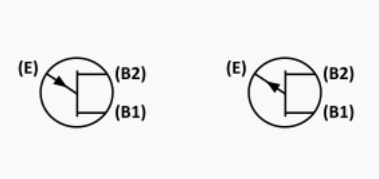
When I first glanced at the HD-16 schematic, I didn’t notice that the transistor was neither a familiar BJT or a FET. Upon closer study I noticed that Q1 is a “unijunction” transistor and was labeled with two bases, B1 & B2 and an Emitter, E.
Schematic symbols for the UJT: N-type on left, P-type on right
My immediate concerns were how rare the 4JX5E670 is, and whether they or a solid equivalent can be found at a fair price today should I need to replace them. My concerns were tempered however by the excitement that this project is going to afford me the opportunity to learn something new.
Up to this point in my life, I have had a cursory knowledge of transistors. I knew the difference between NPN and PNP Bipolar Junction Transistors – their construction and function – and I had a very basic understanding of how a Field Effect Transistor differed from a BJT.
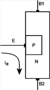
Doing a little Googling, I learned that UJTs could only function as a switch and not as an amplifier. This made sense as the ability to generate pulses would be key to function as an oscillator at the heart of the HD-16.
Structure of a P-type UJT (source: Wikipedia)
Back to the project… assessing the damage.
At first glance, one HD-16 was missing its lamp and the C cell battery holder. The C cell battery holder in the other HD-16 was extremely corroded. Also missing were three of the four 9 volt snaps. One of the 10K tone potentiometers was gunked up and the shaft would not turn. Otherwise, everything else appeared to be present…. not bad.
I grabbed a 10K pot from my on hand parts stock and replaced the seized control and I soaked the other pots as well as the switches with de-oxit and worked the contacts.
I decided to replace the 0.22 uF capacitors with a pair of new Mylar caps from my stock. I did not test the fixed resistors and I didn’t even bother to check to see whether I had any 4JX5E670 UJTs in my parts supply. I would dive deeper and replace any of these parts if the oscillators failed after the other work I did.
I debated whether to replace the lamps with LEDs, a popular and logical mod. Doing so meant I could eliminate the 1.5 volt batteries altogether and complete the mod by adding a dropping resistor from the 9V batteries and rewiring the SPDT switch.
I liked the way the original incandescent dial lamp looked so I didn’t do a mod for LEDs. Since I needed to replace one of the missing C cell holders and the remaining one was badly corroded, I replaced both with modern plastic holders. I attached the new holders to the inside of the cabinets using 3M 2 sided tape.
I was unable to determine whether the HD-16 was a DIY kit or was sold only as a completed unit as I couldn’t find a construction manual online. So I took the time to sketch out the schematic and trace the parts layout creating a pictorial diagram I could use to confirm the circuit was complete.
Putting it all together
I worked on both oscillators side by side, working through each step of the restorations on one unit, then the other. It made sense to work this way as I could stay focused on each step as I worked.
After completing the parts replacement I grabbed some batteries and tested each HD-16 before attempting reassembling. Fingers crossed, both worked fine and I was relieved I didn’t have to address replacing the unobtainium transistors.
One of the completed electronic restorations – ready for testing and reassembly.
Reassembly went smoothly. I started by replacing the lamp grommet and inserting the lamps into their holes on the top of the enclosures and then installing the speakers and grilles.
Next I reattached the springs on the backs of the cabinets – this was Heathkit’s clever idea to secure the 9 volt batteries securely in place – and I stuck the new C cell holders onto the back of the enclosure using 3M double sided tape.
Next I installed the switches, confirming that they were properly oriented to light the lamp when set to “LIGHT,” and then I re-inserted the two potentiometers and the key and phones jacks to the front panel.
The last thing I did before closing up the cabinet was to secure the terminal strip to one of the speaker screws. The space available was tight, but not impossible. I took special care to make sure that the transistor and other component leads weren’t shorting out against each other. I did another test of both units before closing up the cabinets.
Both HD-16 cabinets ‘re-stuffed’ and ready for buttoning up.
Finishing touches
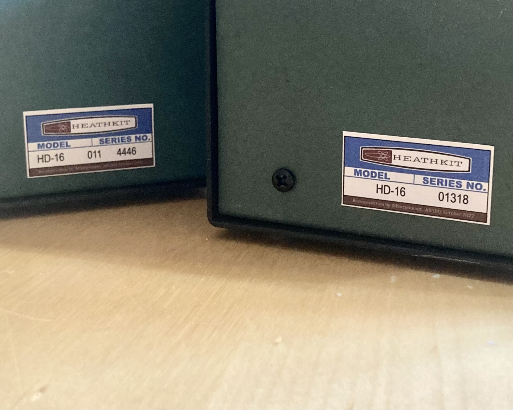
Both HD-16s had the original metal foil serial number sticker stuck inside the cabinets, but they were in bad shape and not salvageable. So I created a “new-retro” style serial number sticker for each unit in order to preserve each CPO’s history.
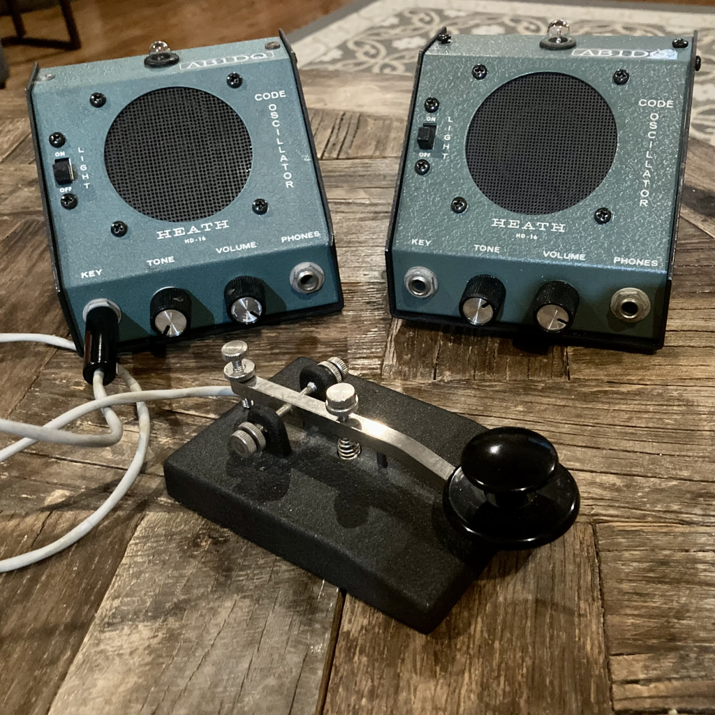
AFTER: Two restored Heathkit HD-16 Code Oscillators ready for use!
Do you or did you have a Heathkit Code Practice Oscillator? If so, which model and how did you like it? Comments and questions encouraged. Drop me a line at james@ab1dq.com to join the conversation!
A fun, easy-to-build, weekend radio kit project that is the latest to get the AB1DQ Cigar-Box treatment.
It’s no secret that as a modern day electronics kit builder, I have a fondness for the fine kits currently being offered by the Four State QRP Group and it’s also no secret that one of the biggest gateways to my ham radio ticket was the years I spent as a SWL in my teen years.
Is it any surprise then, that I would at some point build the 4SQRP Group’s excellent long-running Ozark Patrol Shortwave Receiver? Quoting, their website,
…this kit was designed in homage to simple beginners regenerative receivers of a generation ago. Many current hams and radio enthusiasts were introduced to the hobby by building and listening to such classics as the Radio Shack Globe Patrol, or the Knight Ocean Hopper. … the Ozark Patrol is offered so that the builder of today can relive the excitement of tuning in the world on a simple receiver circuit.
Once again, you’re singing my song 4SQRP – count me in!
About the Kit
Pioneering Radio Engineer & Inventor Edwin Armstrong
While still an undergrad at Columbia University, legendary radio pioneer Edwin Armstrong patented the regenerative receiver in 1914 and it was leaps and bounds ahead of the then state-of-the-art receiver circuit.
By applying some of the output signal from a vacuum tube back into the input signal in phase, a feedback loop is created that greatly amplifies the signal by as much as 1,700 times. A regeneration control is used to gradually adjust the amount of feedback to the point of oscillation where the signal will distort. The regenerative receiver features improved sensitivity and selectivity over other receiver designs of its day.
The Ozark Patrol circuit, designed by David Cripe, NM0S, replaces the vacuum tube of Armstrong’s era with a common NPN bipolar transistor. The kit has only 38 through-hole components for the kit builder to attach making for a build time for me of under two hours.
The Ozark Patrol also features the modified surface mount technique known as the “Pittsburgh Method” of construction, pioneered by Joe Porter, WØMQY. Leaded components are directly soldered to pads on the back copper layer of the circuit board (which also makes the front panel of the radio), forming a ground plane to shield the radio from hand capacitance effects while tuning.
I previously built the 4SQRP Murania one transistor “Boy’s Radio” kit that used the Pittsburgh Method and it was a positive experience. You can read about that build here.
Building the Ozark Patrol
I built the kit in under three hour’s time over a couple of days. As I’ve come to expect from 4SQRP, the kit was well packaged, complete and not missing any parts, and the step by step instructions were for the most part very clear and easy to follow. A couple of times I did find myself referring to photos of others’ builds for clarity – particularly when working with the tuning capacitor and the ‘gimmick capacitor.’
The kit requires the builder to wind a single toroid inductor, 20 turns on a T-50-2 core and its the first step of assembly. Because I started my build in the evening after a long work day, I chose to wind the toroid later when I was feeling 100% fresh, and instead started my build by attaching the resistors, diodes and fixed capacitors.
A novelty feature of this kit is that it requires the builder to wind a ‘gimmick capacitor’ to couple the antenna to the tuning capacitor. This low value capacitor is easily made by twisting about an inch of magnet wire with insulated hook up wire. I had no difficulty doing this, and I apparently did it correctly as my receiver worked the first time.
My hand wound gimmick capacitor and toroid can both be seen above.
The instructions suggest that the radio can be made or less selective by tightening or loosening the twist so I may choose to experiment with this. Fellow kit builder and blogger, Mike Simpson, has a really great post about his build of the Ozark Patrol here in which he describes his mod adding a varicap in lieu of the gimmick cap for coupling and tuning the antenna. Check it out!
The Cigar Box Treatment
The Ozark Patrol comes with a slab of soft pine wood which is intended to be used as a base. The circuit board/front panel is screwed to the board at 90 degrees leaving the guts exposed for viewing and the easy attachment of the antenna and ground wires.
I initially envisioned mounting the radio on the top or the bottom of a cigar box and attaching a handle to fashion a finished radio resembling a portable transistor radio of my childhood years.
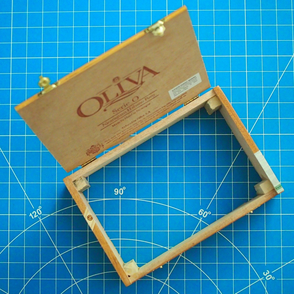
Looking through my stash of cigar boxes I found an Oliva box with a hinged lid that had almost the exact dimensions of the Ozark Patrol circuit board. What good fortune!
Using a box cutter, I carefully pried off the bottom of the box and then smoothed the edges, removing excess dried glue with a fine grit sandpaper.
The location of the screw holes on the circuit board unfortunately were spaced to fall just inside the edges of the cigar box sides. I addressed this by adding square dowel reinforcements to the four inside corners of the box using wood glue. Once dried and set, the dowels provided both a space to drill pilot holes for the PCB screws and reinforcement for the box itself.
My cigar box with the bottom removed and the corner reinforcements glued in place.
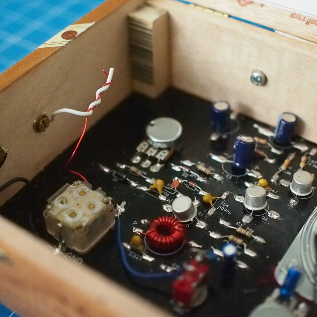
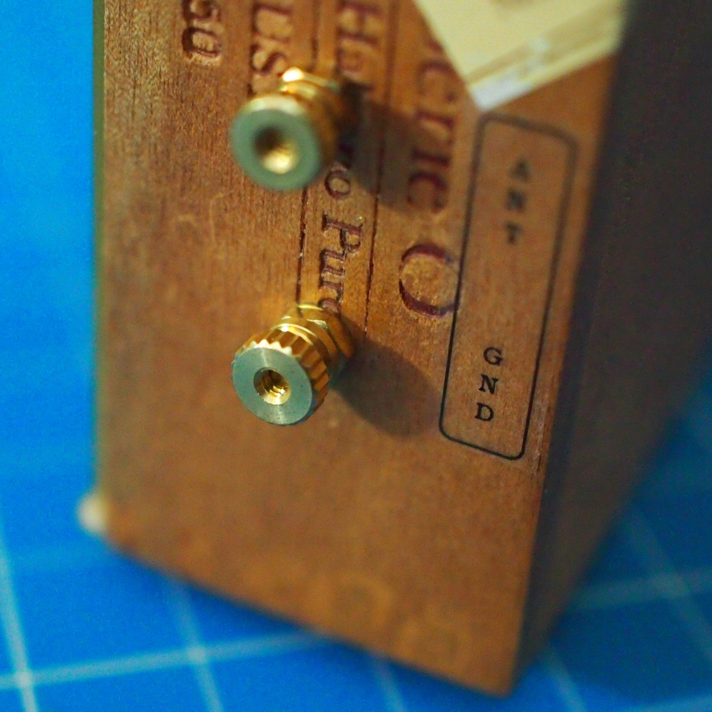
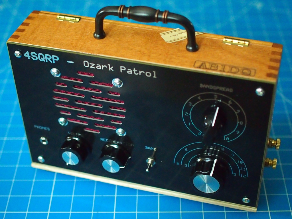
Finishing touches included using brass thumb screw hardware mounted to the side of the box for retro- looking antenna and ground terminals and attaching a decorative drawer pull to the top to provide a carrying handle.
Brass thumb screws for antenna & ground wires.Inside my finished Ozark Patrol.
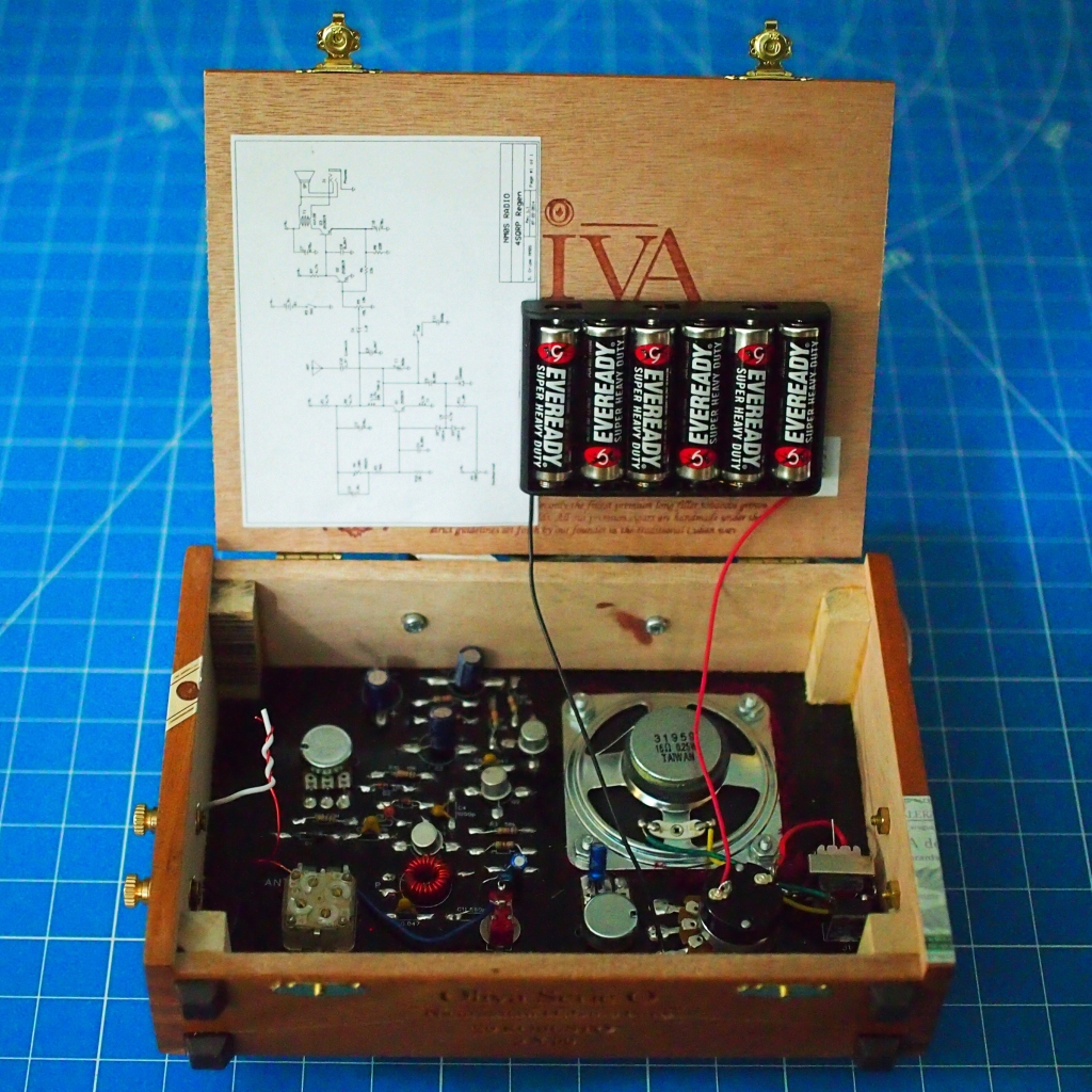
Inside, I attached the 6 AA battery holder to the box lid, making sure that I left sufficient slack in the leads for the lid to open completely. I also cemented a copy of the schematic inside the lid. In the end I have a very retro- looking suitcase shortwave radio that has a bit of resemblance to portable radios like the Zenith Trans-Oceanics of an era gone by.
How did it work?
Last night I set the radio up in a second floor bedroom, attaching a ground wire running to the ground lead of a power outlet and a random length of wire for an antenna suspended to the light fixture. I also shut off the LED room lights which made a difference in lowering noise.
Tuning the radio was definitely a fiddly process, but it was also a ton of fun. I easily picked up 3 or 4 AM shortwave broadcasters on one band and hams operating CW (Morse Code) on the other. Success!
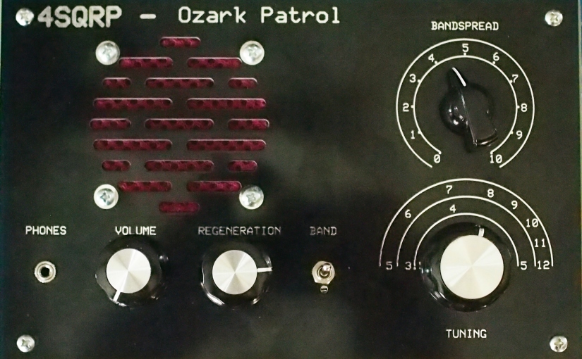
My completed Ozark Patrol – looks great, works great!
In Conclusion
I would highly recommend the Ozark Patrol kit for any kit builder, or aspiring kit builder. The kit shouldn’t present too much of a challenge for even a new kit builder and the finished radio works and is fun to operate.
Have you built the Ozark Patrol or a similar kit? Perhaps you built the Radio Shack Globe Patrol back in the day? Please leave a comment or drop me a line at james@ab1dq.com to share your experience!
APRIL 2024 UPDATE: Check out Kevin Behn, K0KLB’s YouTube video of his build of the Ozark Patrol here. Great work Kevin!
Have you built the Ozark Patrol? Please share your experience with us!
“Creativity is inventing, experimenting, growing, taking risks, breaking rules, making mistakes and having fun.” ~Mary Lou Clark
Ham radio is unlike and superior to all other hobby radio services as it not only allows licensed operators to build, test and experiment with our radios and other equipment, we are encouraged to do so.
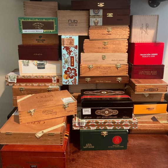
Long before I earned my ham radio license, I’d spend hours on end as a child creating various projects fueled by my imagination, using the never ending supply of empty cardboard Dexter cigar boxes my grandfather had stashed in our basement.
Several of my creations in my early adolescence involved radio & electronics projects. Besides providing me with a stash of cigar boxes to play with, my grandfather also had a fairly complete electronics workbench in our basement, complete with tools, tubes, parts, dozens of radio & TV carcasses in various states of disrepair and a treasure trove of 1960s era magazines including such titles as Pop Electronics. My grandfather had also taken the DeVry Home Radio & Television course before I was born and to my delight, all of his workbooks and home projects were under the workbench.
As a licensed ham radio operator for the last 20 years, one of my favorite aspects of our hobby is kit and scratch building and operating with QRP gear I’ve built myself. Over the years I’ve built projects into aluminum chassis, atop breadboards, in tuna tins and even tiny mint cans. Following in my grandfather’s footsteps in yet another way, I’ve become something of a cigar aficionado in recent years and found myself amassing my own stash of cigar boxes. It wasn’t too long before inspiration struck and I put one and one together.
Why the Cigar Box Chassis?
My cigar box fascination blends two of my leisure loves – radio & cigars. It also gives me the opportunity to challenge my creativity and express myself through unique projects. Building with cigar boxes also connects me to my childhood roots, per above, as well as the very roots of amateur radio, taking me back to the early era of breadboarding. Finally point-to-point construction using terminal strips and increasingly rare leaded components is not only ‘going retro,’ it’s also a lot easier on us older folks. While the parts got smaller, our vision got weaker and our hands a bit shakier!
There are several advantages a cigar box chassis brings to your project, such as:
adding flair & artistic touch to the project,
being available in different sizes and shapes,
being much easier to drill and cut than metal chassis,
being easily oriented in various ways to accommodate specific project needs.
having multiple construction planes – the top & bottom of lid, and the bottom of box.
providing space to store cables, accessories, and documentation inside the box.
Conversely, there are a few disadvantages to be aware of when building a project into a cigar box, such as:
varying quality of construction,
cheaper flimsy boxes may be difficult to drill and cut cleanly,
boxes with thicker lids and sides, make the mounting of some parts difficult,
lacking the inherent shielding and common ground plane of a metal chassis,
hinged lids may make for challenging parts placement and wire routing.
“The creative adult is the child who survived.” ~Ursula Le Guin
Inspiration
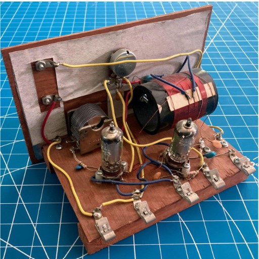
There are several contemporary kits that I became aware of that helped spark my imagination for my cigar box builds. These included the very fine line of Peebles Originals kits which featured point-to-point construction on a wooden base. I had build a few of the Peebles kits including a one tube regen receiver I built with my 12 year old niece a few years ago.
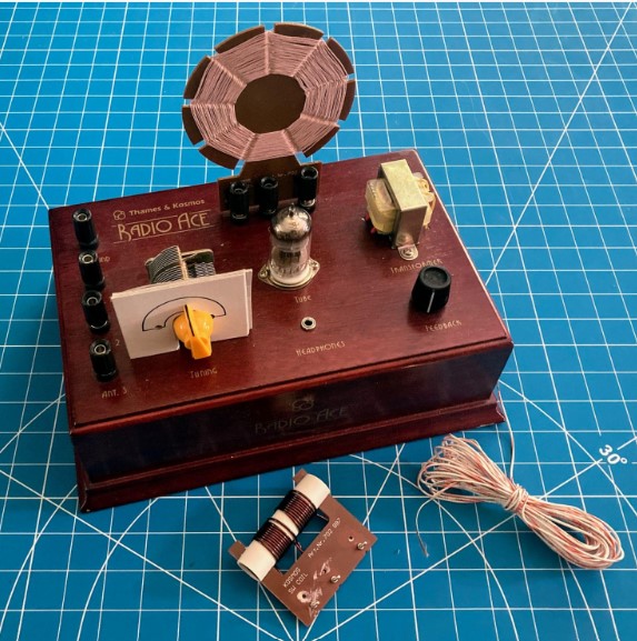
My good friend, and radio cuckoo soulmate, W1YSM, Dr. Ed Snyder, gave me a wonderful gift a few years ago, the Thames & Kosmo Radio Ace, a mid-2000s one tube regen BCB & SW receiver ‘kit’ built into a nicely finished wooden base. This wonderful kit didn’t require assembly but came with a wonderful step-by-step book explaining how radio and this specific circuit works.
Inspiration also came from the Four State QRP Group’s venerable Bayou Jumper QRP transceiver kit, which is a scaled down solid state replica of a WW2 era ‘paraset‘ rig. The kit is intended to be built into a wooden suitcase box.
Sources of inspiration from L-R: a Peebles Original 1 tube regenerative receiver, the 4SQRP Bayou Jumper transceiver, the Thames & Kosmo Radio Ace.
Where to find cigar boxes
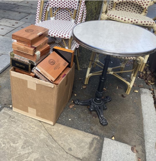
The best place to find cigar boxes is your local cigar shop. Search for them in Google and call around. Better yet, pay your local shop a visit. I have gotten all the boxes I’ve ever needed from the Owl Shop in New Haven (where I’m a regular customer). The Owl Shop puts out dozens of cigar boxes on the curb each week and they are free for the taking. Some shops will charge you for empty boxes and in my experience, you can find great boxes for under $10.
My source & happy place!Every week at the Owl ShopAB1DQ’s not so secret stash
Online sources for cigar boxes include eBay and Etsy as well as craft suppliers such as Michael’s, Hobby Lobby and cigar box guitar kitter CBGitty.
Tools for the job.
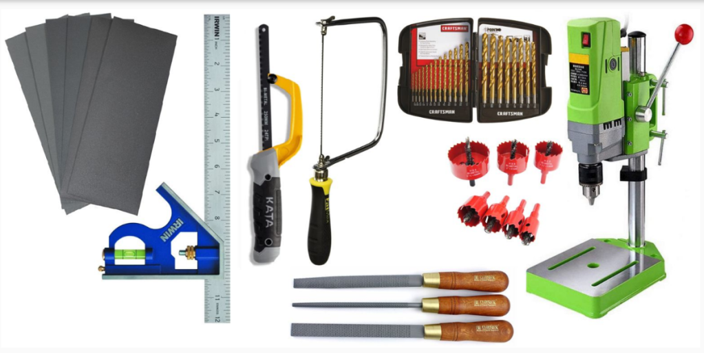
In addition to your usual electronic kit tools (solder iron, nippers, pliers, screwdriver) you will need some basic woodworking tools for preparing the cigar box.
Basic woodworking tools.
A small drill press with a set of hole saw bits will go a long way in terms of being able to drill neat and precise holes for mounting speakers, meters, tube sockets and holes for switches, potentiometers, varicaps and power, antenna and key sockets.
You will also want to have a small hacksaw and coping saw, files and sandpaper. A square with level is essential for precisely locating the places you want to drill.
I also recommend having a good set of drawing tools that include rulers, compasses and protractors. I am a huge proponent of taking the time to sketch out your box layout and design before drilling any holes. I keep a lab notebook in which I document all of my projects. This is taking the adage, measure twice, cut once to the next level. It’s time well spent and in the end you will have a nice record of your projects, not unlike your logbook of on air contacts.
Invest in some basic drawing tools and graph paper to help with planning your layout
Keys for success
Proper planning is the biggest key to success, but other keys include:
Keep & use a workbench notebook. Document all aspects of your project and sketch the circuit, parts and chassis layout. When laying out placement of parts, measure and remeasure. Then measure again.
Challenge yourself to k three-dimensionally. You have several planes on a cigar box in which to place parts – the top and bottom of the hinged lid, the bottom of the box, and the inside and outsides of the four sides.
Prototype whenever possible!
Keep leads short, but allow enough space for troubleshooting and future mods.
Keep damaged boxes for properly sizing holes for future projects.
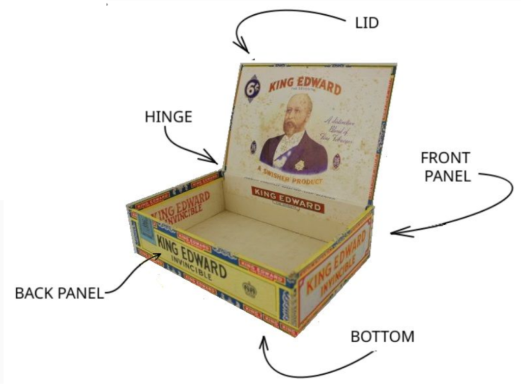
Cigar box anatomy and project layout
Start by considering the cigar box from all angles. Turn it over and rotate it and imagine how you want the finished project to look. Consider various placements of parts, controls and circuit boards or terminal strips. Keep the end user in mind and consider ease of use and ergonomics.
You need to pay special attention to the location of the hinge for boxes with hinged lids. The hinged edge is the only place you can route wires from the lid to the bottom or other sides of the box. The back side of the box will logically become the front side of your project where you may want to place switches and controls.
You will also need to be mindful about the depth of parts, measure for adequate room and alignment of all parts when the lid is closed. Consider too that cigar boxes are sometimes made of thin wood and weren’t intended to contain or support heavier components like transformers. Support and balance are both important. You may wish to reinforce the lid or sides by gluing in square dowels. You can also add corner reinforcements found at your local hardware store for additional reinforcement.
Relocating controls off of the PCB
Many modern kits have switches, pots and other controls mounted along the edge of the printed circuit board and are intended to meet the front panel of an enclosure. Sometimes this makes for an easy way to mount a project inside a cigar box. Another option is to move or replace these parts with chassis mounted parts that you can reposition on the front or top of the cigar box. This gives you more flexibility in terms of control placement.
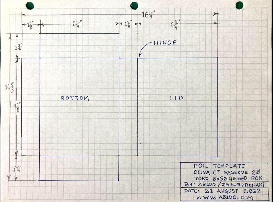
Shielding
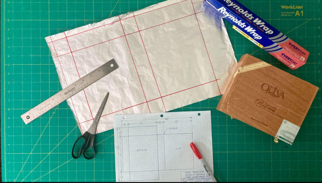
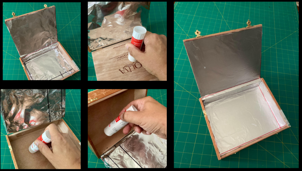
Being non-conductive, your wooden cigar box won’t provide shielding like a metal chassis. This may lead to problems in terms of hand capacitance or interference from other nearby appliances that generate RF. Lining the inside of the cigar box with a layer of heavy duty foil can help. Foil is easily cut & sized and adheres quite well with white glue or a glue stick. Heavy duty aluminum foil is good and cheap, and copper foil is even better but costs more.
I recommend measuring the inside dimensions of your cigar box and then sketching out a pattern on graph paper. Then, using a cutting mat and ruler, transfer the pattern to the foil and carefully cut the foil. Then, starting from the bottom of the box, use glue stick to apply the foil.
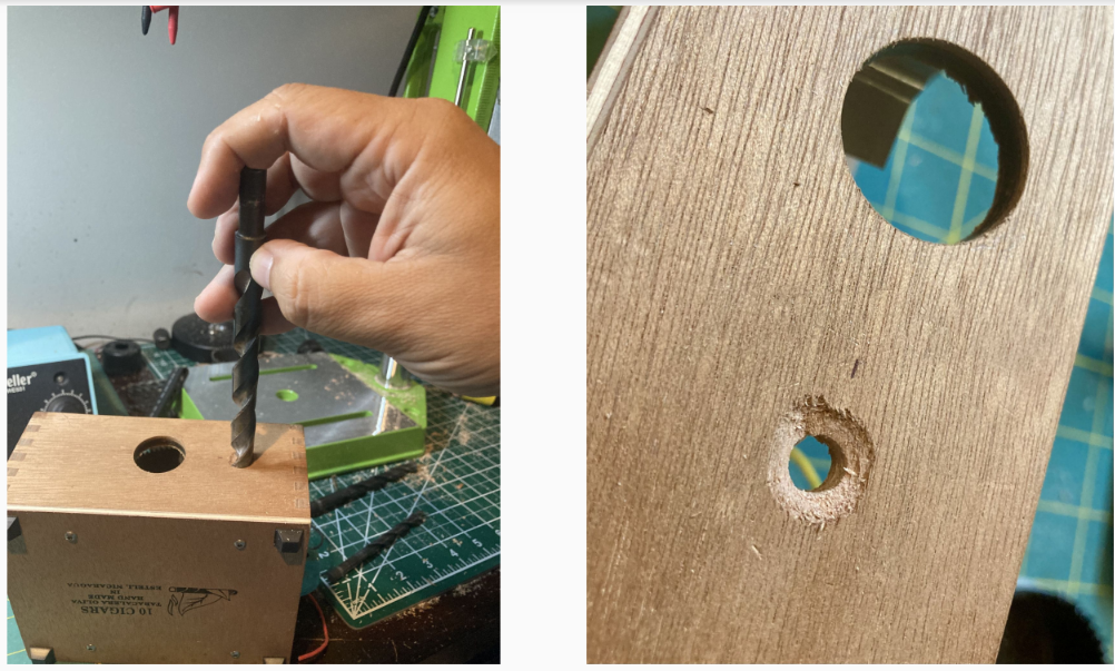
Countersinking holes
Potentiometer and varicap shafts, switches, and other chassis mounted connectors may be too short or shallow for thicker cigar box lids or sides. One solution is to countersink a larger diameter hole on the outside of the box to provide space to flush mount a lock washer and nut. However, many cigar boxes feature soft wood which may easily splinter. When enlarging a drilled hole in soft or thin wood, use a larger drill bit and turn it gently by hand.
“You can’t use up creativity. The more you use, the more you have.” ~Maya Angelou
Some selected AB`1DQ creations
To perhaps help spark your imagination and as a means to illustrate some of the construction points I outlined above, the remainder of this article showcases a few of my cigar box projects.
Basic Code Practice Oscillator
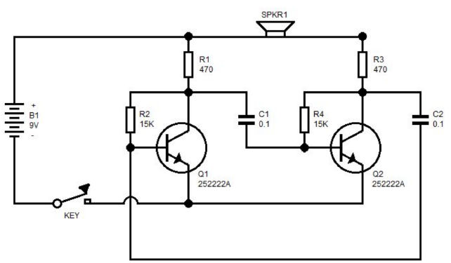
I recently built a basic 2 BPT code practice oscillator using the Boy Scout WN0BSA schematic found all over the internet and sketched out my parts layout using Windows Paint.
This project was a bit of pure nostalgia for me as my first childhood cigar box build was a simple transistor CPO similarly mounted in the same fashion with the key attached to the lid in an old Dexter cigar box.
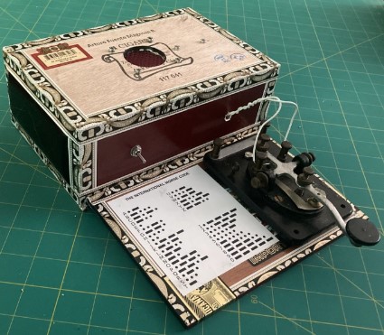
For a simple old school project, I decided to use a pair of terminal strips mounted on the bottom of my cigar box. My CPO layout pushes the abilities of the cigar box a bit further. Choosing a cigar box with a flat lid that folds out flat to the rest of the box when opened and placed upside down, I mounted a J38 key to the lid and pasted a copy of the International Code next to it. With the speaker also mounted to the bottom of the box, the end result is a nifty flip open all in one CPO.
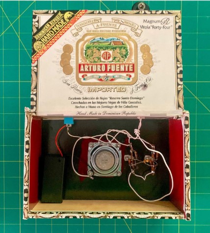
The completed CPO inside….. and out.
This project was a bit of pure nostalgia for me as my first childhood cigar box build was a simple transistor CPO similarly mounted in the same fashion with the key attached to the lid in an old Dexter cigar box.
QRP Guys 40 Meter Easy Receiver
I loved the basic kit offerings from the folks at Pacific Antenna. A few years back, along with my fellow advisors to the Amateur Radio Club at Yale, we led a Wednesday Night Workshop at the Yale Center for Engineering Innovation and Design.
The workshop was intended to introduce the uninitiated Yale students, faculty and staff to the basic principles of RF and after a brief presentation, the group paired up and each team built the Easy Receiver Kit. Despite the fact most had never soldered, in the end we had successfully built 10 out of 10 kits. The students in particular were overjoyed when they were able to hear their radios oscillate on an HF rig we brought in.
The Pacific Antenna Easy Receiver is a great kit and a great value at it’s current retail price of $25.00. Order yours here.
I decided to give my Easy Receiver the cigar box treatment and mounted it in a small CAO Perfecto cigar box. This is an example of where I measured and drilled out properly spaced holes in the cigar box lid so I could mount the lightweight PCB using just the shafts of the potentiometers.
I added an 8 ohm speaker to the lid, a switchable 3.5mm audio out jack for the use of phones, along with a chassis mounted coaxial barrel power connector, an on-off switch and a power on LED indicator.
The simple QRPGuys Easy Receiver mounted with speaker in a CAO cigar box.
Utilitarian LM386 Audio Amplifier
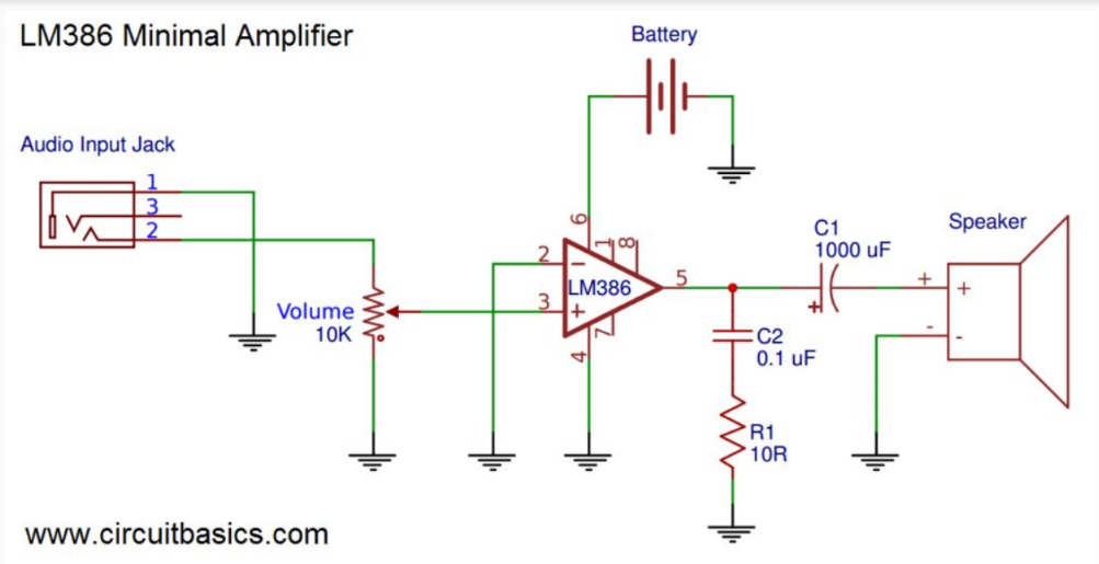
The LM386 audio amp IC makes it simple to add an audio stage to any receiver project. The chip requires no more than a handful of passive components to build a robust amplifier and the internet is flush with schematics and plans. Here is a schematic for the most basic LM386 audio amplifier, taken from the www.circuitbasics.com website.
If you don’t have the necessary components on hand in your parts bin, there are many kits available online with the PCB and all necessary components, aside from the speaker. Prices range from about $10 from US retailers and can be found literally for pennies offered by Chinese retailers like AliExpress.com
While I have incorporated this amplifier into some of my receiver projects, I have also come to appreciate the value of having a standalone amplifier on the operating bench.
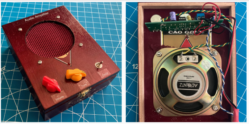
Here’s a cigar box build from a kit that also includes a tone control. Again, I mounted the PCB directly to the lid of the cigar box measuring and drilling holes to accommodate the board mounted potentiometers. The SPST toggle power switch is chassis mounted and placed in line with the volume and tone control.
Transistor Tester
The “transistor tester” kit is fairly ubiquitous online these days and as a frequent kit builder, I have found it to be an indispensable tool when working with small leaded components given their shrinking size and my diminishing vision as I get older. The tester has three terminals to which you can attach resistors, capacitors, inductors, diodes and transistors. The 2 line display returns the type of component and its value and will even indicate the terminals for diodes and transistors.
I built my transistor tester into a cigar box, mounting the display, controls and the terminals to the top of the box. I used three 6-32 screws for the terminals and they are spaced so I can hold most 2 leaded components directly to them for testing. I store three alligator clip jumper cables inside the box when not in use so they are at the ready for short components or when testing three leaded components like BJTs.
I made a couple of mods, replacing the on board trimmer pot that controls display contrast with a same value chassis mounted pot and I moved the power on LED from the PCB to the cigar lid as well.
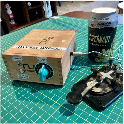
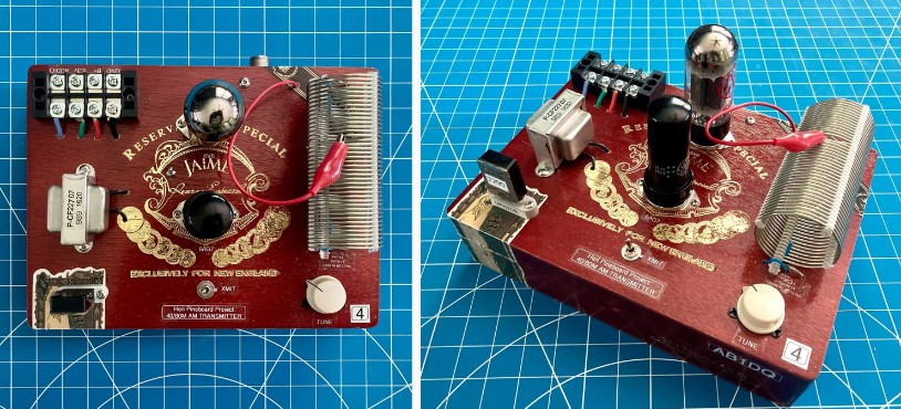
Ramsey QRP-20 CW Transmitter
Ramsey was a prolific retailer of simple electronic kits and offered a wide variety of ham radio kits as well as other non-radio projects. Their products featured a nifty two piece black plastic project box with pre-drilled end pieces to accommodate the controls for the specific project.
I had built several of their kits over the years, but sadly it’s been a while as the company abandoned the hobby kit business several years ago.
This past winter I spotted an unbuilt Ramsey 20M transmitter kit available online at a not-so-unreasonable price. I purchased it and really enjoyed putting it together. The kit came with the black plastic enclosure, but I realized the dimensions of the PCB were nearly a perfect fit for the inside of the small Oliva Nub cigar box.
My cigar box treatment of the QRP-20 transmitter
I have already blogged about my build, which you can read in detail here.
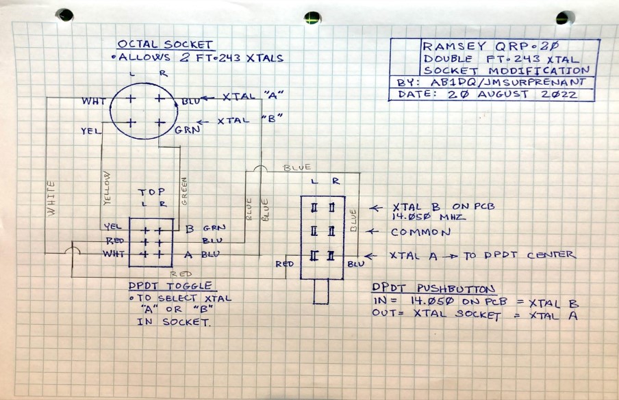
Since my build, I I made a mod in order to give me not two, but three selectable frequencies. I added an octal tube socket to the left side of the cigar box and installed another DPDT toggle switch. The octal socket will accommodate two FT243 crystals so by wiring per my diagram below, I now have a versatile QRP rig.
My sketch for the mod. I typically draw in fixed components in ink, but then rely on pencil for adding wiring routes and measurements. I nipped the unused four terminals from the octal socket before installing it.
L: My original kit build. R: Same project now modified with an octal socket and DPDT for 3 on board crystals.
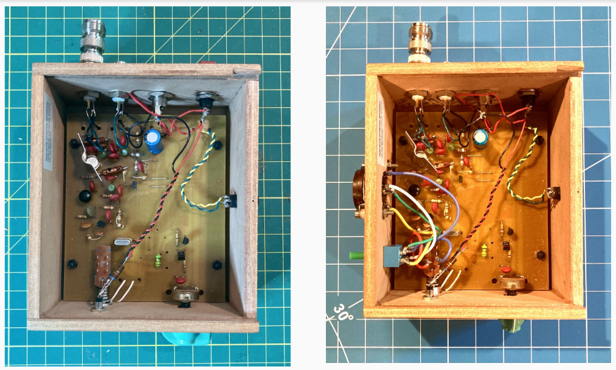
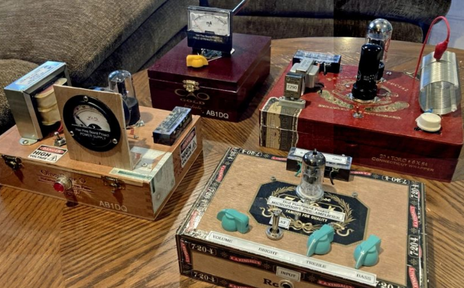
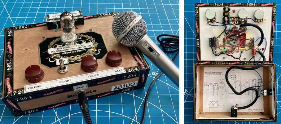
The Heil Pine Board Project Reimagined
My cigar box interpretation of the wonderful Bob Heil Pine Board Project.
Many folks reading this may already be aware of the Pine Board Project, an old school DIY AM transmitter project with four distinct sub-projects – field strength meter, power supply, audio pre-amp w/ equalization and the transmitter itself.
About five years ago (my how time flies!) Bob Heil presented the projects with step by step instructions and updates each week on the HamNation podcast. And the project was also featured in QST, and on Heil Sound website.
I initially built the project as originally presented on slabs of pine wood but then converted my build into cigar boxes. As with the Ramsey QRP-20 above, I have already blogged about my transformation of the power supply here.
I plan to revisit my build and expand my blog post on the rest of the project in the future, but in the meantime, here are some photos of my cigar box mods.
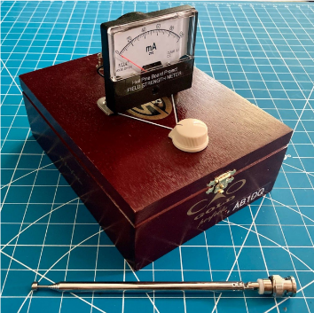
Project 1: The Field Strength Meter
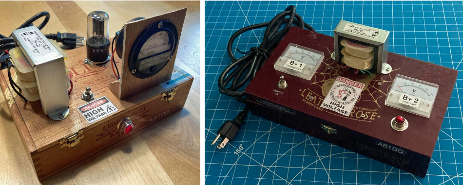
Project 2: The Power Supply L: The original tube based power supply R: The revised version using a solid state rectifier.
Project 3: The Audio Pre-Amp & Equalizer. (Note the long route for the audio in cable. This would have been better placed under the hinge making the back of the box the front of the pre-amp. The cable is shielded coax, however.)
Project 4: The completed AM transmitter for 40 & 80 M. I am planning to mod this to add CW.
The Takeaway
Ham radio is unique among all radio-service hobbies as we are not just allowed, but encouraged, to build our own gear and to experiment.
Working with cigar boxes scratches my creative itch as I build gear that is uniquely me.
Where will you find your niche? My charge to you: GO MAKE STUFF!
Thanks for taking the time to read my article. If you enjoyed it or have further questions or want to share ideas or want to leave any other feedback, please leave a comment below or feel free to drop me a line at james@ab1dq.com.
I would love to hear what is on your workbench these days!!!
As I venture deeper into scratch building I’ve recently become aware of how useful it would be to have an old school dip meter on the workbench to verify the resonance of LC circuits in the receiver circuits I’ve been experimenting with.
In the back of my mind I’ve always been aware of the existence of the dip meter and the tube era term “Grid Dip Meter” seems to have been rooted in my mind going back to childhood. I’m fairly certain the term appeared on amateur licensing exams I’ve sat for, and I know it was ubiquitous in many of the old 60s era Pop Electronics I used to read in my grandfather’s radio shop.
I started a search online to learn more about the history, design, use and availability of dip meters, sometimes called ‘dippers’ today. In the solid state era, field emission transistors (FETs) and sometimes bipolar junction transistors (BJTs) have largely replaced .
FUN FACT: FET based dippers are sometimes called Gate Dip Oscillators while BJT based dippers are sometimes called Emitter Dip Oscillators.
The dip oscillator isn’t a precision instrument by today’s digital standards and several factors could lead to inaccuracies. Despite that, it has numerous practical uses in the amateur radio station. In addition to being used to measure the properties of resonant circuits, filters, and antennas, a grid dip oscillator can also be used as a signal generator, to measure individual component capacitance or inductance and they may also be used for transmission line testing.
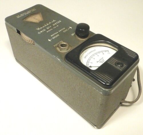
I discovered that back in the day, the amateur radio builder had several options to assemble their own GDO from kits. As expected, Heathkit offered several dippers in kit form throughout their history including the Model GD-1 and later, the HD-1250.
Heathkit Model GD-1BHeahtkit Model HD-1250
I found several of these old Heathkit GDOs available online and at pretty reasonable asking prices. But as always, when buying used vintage electronic gear, it’s a crap shoot in terms of whether the item bought sight unseen will come complete and be operable. So I decided to explore whether any of the niche kitters offered a modern day equivalent that I could build myself.
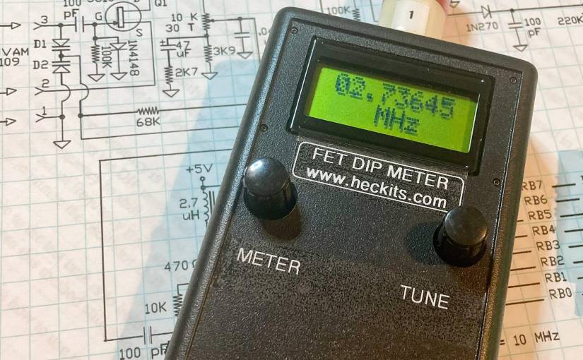
This is where I discovered HecKits (www.heckits.com) operated by kit designer and ham radio operator WA7OIB, Darrel Heckendorf. Darrel offers several kits priced under $100 that may be of interest to the QRP builder including an SWR Bridge/Frequency Counter, a Step Attenuator, a CW Keyer, and of interest to me, an FET Dip Meter.
I ordered the FET Dip Meter kit online and quickly received an email from Darrel, thanking me for my purchase, asking me to confirm my shipping address and to inquire whether or not I wanted him to include the optional 6M coil. I had initially missed this email and by the time I replied a day later, I had discovered Darrel had already shipped the kit with the 6M coil at no extra charge and the kit arrived a couple of days later… wow!
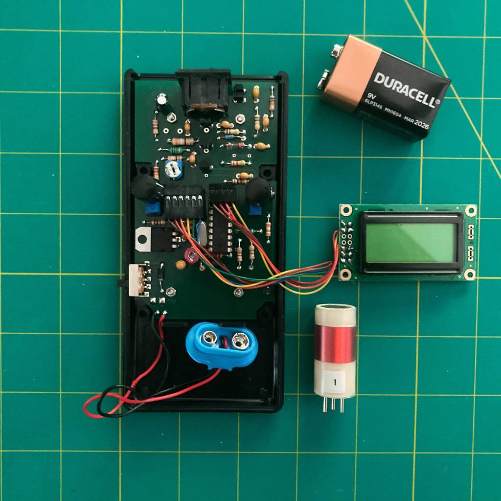
I sat down to build the kit this weekend and it was the perfect project for a relaxing Saturday afternoon at the workbench. My initial HecKit experience was everything I look for in kit building.
The kit was well packaged and parts were in clearly labeled zip lock bags. The quality and the fit and finish of the PCB and project case were exceptional. The plastic case fit together precisely and has a nice quality feel about it. The PCB was not thin and flimsy and it featured double sided holes. While it did not have silk screening for parts placement, that was not a problem because the instructions included a large easy to follow diagram of parts placement on the PCB.
Overall, the instructions and documents which Darrel sent by email as a PDF along with my order confirmation was exceptional. Darrel provides a nice introduction to the product and includes several links to learn more about the theory and operation of the dip oscillator and the step by step directions are very easy to follow. Documentation included not only the PCB parts placement diagram, but also full schematics and very clear easy to understand directions for winding the interchangeable coils.
I give Darrel and HecKits high marks for putting together what I would consider a perfect DIY kit. It’s worth mentioning too that the kit came complete with no parts missing.
From start to finish I spent less than 3 hours on the build with the exception of winding the coils, which I still need to do. Generally I don’t mind winding toroids and coils, but the coils for this kit are just a bit small and a tad fiddly for my aging eyes and increasingly shaky hands to easily manipulate, so I thought I’d complete the other coils later on this weekend when I’m feeling fresh. The kit did come with the first coil covering the 1.3 – 2.8 MHz range pre-assembled and it allowed me to verify that my meter worked properly upon completion of the build.
My completed kit which came nicely together in less than 3 hours on a Saturday afternoon.
If you’re a QRPer and a builder like me check out Darrel’s offerings at www. heckits.com. As I mentioned, there are several other projects on his site that have caught my eye, particularly the Step Attenuator and the QRP mW meter. I look forward to putting my dipper into use on the workbench as well as my next HecKits build.
Thanks for taking the time to read my blog today. Please leave a comment and let me know if you’ve built this kit or any other of the HecKit lines or share your experience with using a dipper in your station.