
My favorite scratch build of 2018 was the capacitor discharge tool designed by and published by Mr. (Paul) Carlson on his Patreon website, Mr. Carlson’s Lab.
Mr. Carlson’s Lab is the best YouTube/Patreon channel I have found dedicated to electronics repair, restoration, building and most importantly, theory. His lab is simply amazing, his expertise is second-to-none, and his willingness to share what he knows is beyond generous.
Paul’s presentation style is easy to follow and well-paced, making the material easy to absorb and his attention to detail borders on obsessive. He not only guides the viewer through construction step-by-step, he takes the time to explain the theory behind each circuit and occasionally challenges the viewer to solve problems along the way.
There is simply no better place to gain a quality electronics education at any cost. Many of the Mr. Carlson’s Lab videos are available for free on YouTube, but for those like me, wanting to learn and know more, Mr. Carlson offers an in-depth electronics course via Patreon. The capacitor discharge tool I built was presented on the Patreon site in a pair of videos.
In the first video, Mr. Carlson introduces the concept and specs and provided the list of components needed for the build, He challenged his viewers to attempt to design the circuit themselves and the best viewer circuits were showcased in the second video where he revealed his design for the project followed by step by step build instructions.
The circuit is composed of four 1k 50 w resistors wired in series to provide a load to drain charged capacitors. There are two LEDs wired in parallel with dropping resistors and a 5.6 v 5 w Zener diode to control current direction. Depending on polarity, one if the two LEDs will light when the probes are connected to the cap and will dim out as the cap is discharged. The other set of probe leads us into a standard voltmeter to show the cap charge. This way I can be sure when the cap is safely discharged.
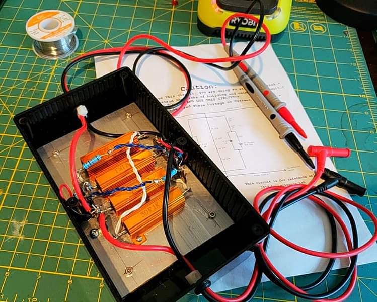

My finished and tested project is shown above. By connecting the output probes to my Ohm meter and getting a 4K ohm reading, I confirmed the load resistors were properly wired in series. For the next test, I shorted the input probes and watched the ohmmeter drop to zero, confirming that the probes were correctly wired and were not open. Lastly, switching the VOM to the DC voltage scale and applying the same input leads across a 9v battery I could read the 9v on the meter and observe one of the LEDs lighting up. Then reversing polarity of the probes on the battery the other LED lit confirming proper wiring of the circuit.
Do you subscribe to Mr. Carlson’s Lab? Have you built any of his original projects? Can you recommend any other YouTube channels for learning electronics? Please add your comments below or drop me a line at ab1dq@protonmail.com.

not nearly as precise and a bit more exciting to use.
©2019 James M. Surprenant

Which LED’s did you use? Supposedly they are required to be ‘very bright – sensitive’; and can be lit by very small current (as demonstrated by Mr. Carlson’s holding one side of the LED and placing the other LED lead to a 9v battery.
LikeLiked by 1 person
Hello D, thanks for commenting.
I believe I used a pair of CO RODE ultra bright white 5mm LEDs (Diffused White) rated at 3.0 – 3.2 V forward voltage @ 20 mA. I found these in an archived Amazon order from about the time I built the kit along with the 50 watt resistors. The LEDs are on Amazon here
Good luck!
LikeLike