

MY FALL 2024 ANTENNA PROJECT
One of the best things about autumn is that after the pretty leaf-peeping season ends early in the month, there are several weeks of pleasant enough weather and the lack of leaves makes launching wires into tree branches so much easier. Thus, for many hams like myself, installing new antennas and repairing damaged existing ones is as much a fall tradition as football and pumpkin spice.
Last Spring I attempted to install an End Fed Half Wave Antenna cut for 40 – 10 meters running from the window of my 2nd floor shack across the yard and terminating in the upper branches of a dead tree on the edge of the backyard.
Building the simple antenna was a piece of cake. I built the HFKits 49:1 EFHW transformer kit (also available from the ARRL) and cut a 66 foot piece of wire (roughly half the wavelength of the 40-meter band.
However, I failed spectacularly in attempting to get a line up into tree. I had been using a pistol crossbow with an attached spinning reel but despite all of my best attempts I could not place the line where I wanted it.
Losing my race against time as the spring foliage began coming in, I opted instead to orient the antenna with a downward slope to a terminal point about 15′ up to the base of a tree bordering the woods.
The antenna worked – I mean we all know EVERYTHING resonates – but it was a disappointment. The antenna also lacked a choke and was very noisy. I was also remiss that I couldn’t operate on 80 meters.
So, the summer of 2024 passed. It was a good summer in many ways, but I didn’t operate much from the home QTH. I enjoyed several POTA activations and set my sights on the fall antenna season to improve my EFHW.
When September rolled around I spent several weeks watching dozens of YouTube videos and reading articles on constructing a shortened end-fed half-wave antenna that would resonate on a portion of the 80M band and resolved to properly erect the improved antenna.
NOV. 2: CHOOSING A DESIGN & WINDING THE INDUCTOR
In researching EFHW physics and construction, I found VK4YE’s YouTube presentation on his 5-band EFHW which resonates over a narrow swatch (@ 100 kHz) of the 80mb by including a loading coil trap. I found similar plans on several other websites but most called for a 110 uH trap. VK4YE’s design called for a 70uH inductor. Appreciating his comprehensive and thorough description of the design, I decided to work directly from his plans and began gathering my materials.
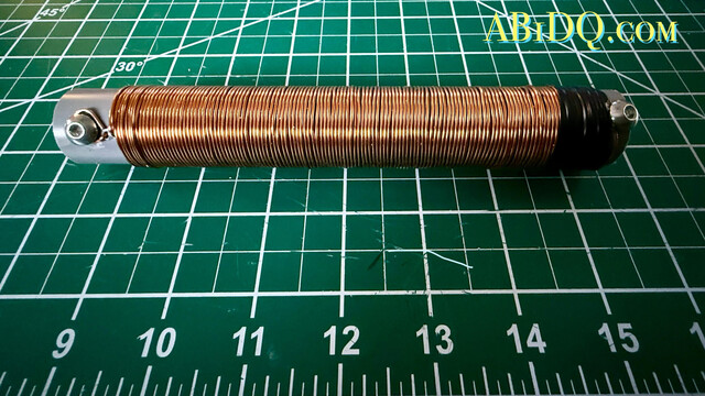
The directions call for 120 turns of 1mm magnet wire on a 25mm coil form. I am that strange fellow who actually enjoys winding coils, don’t ask me why. I’m pleased with my work – I measured the coil and found it to be right around 70 uH. My only failure was that I cut the PVC ever so short before making the windings (see photo). However, I believe it will work fine, and the coil will be shrink-wrapped before being hoisted up.

NOV. 4: TESTING THE TRANSFORMER & CUTTING WIRE
Today I completed construction of the antenna itself. Winding the coil was the most involved step and all that remained was to cut the wire lengths to spec and attach it to the inductor using a pair of dogbone insulators for strain relief.

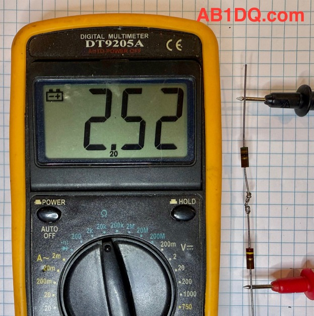
I also tested my 49:1 transformer tonight to confirm that it is functional and that the impedance is correct.
I placed a 2.5K resistor load across the output and ground and used my RigExpert antenna analyzer to read SWR which was consistent at about 1.5 or less across all bands from 80 to 10M.

NOV. 9: TUNING THE ANTENNA
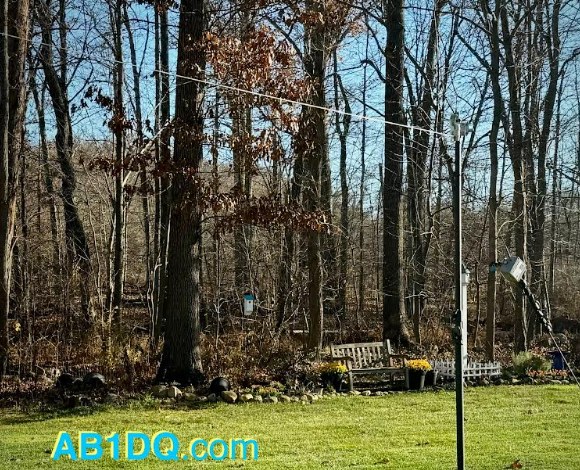
Taking advantage of another great weather Saturday, I strung up the end-fed antenna in the backyard to tune it up today.
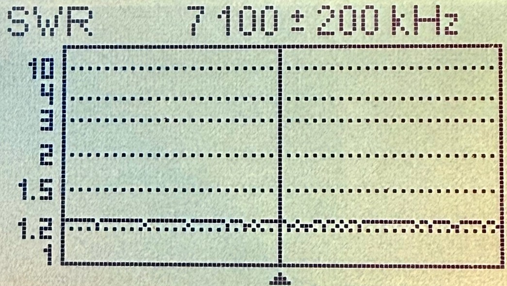
I was very pleased to see SWR readings of 1.5:1 or less on all bands except 80M, which was to be expected. All the documentation I researched about the 80-10m EFHW design stated that while the loading coil allows for resonance on 80 meters, only a narrow portion of the band will tune with a low SWR and it is essential to choose which portion of the band you want to resonate.
As I prefer operating CW on HF, I aimed for the lower portion of 80 and I found shortening the “C” segment of the antenna by 12″ brought the SWR down to less than 2:1 on the CW portion of the 80-meter band. See my SWR readings before and after trimming the antenna in the table below. The segment lengths are in inches.


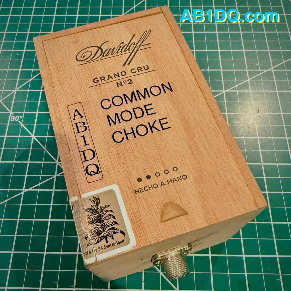
NOV. 10: CONSTRUCTING A COMMON MODE CHOKE
On November 10, I built the final component of my new EFHW antenna, a Common Mode Choke, or CMC. It is highly recommended that a choke be used with an end-fed antenna to prevent the shield of the coax feedline from becoming part of the antenna system and radiating RF unintentionally.
I built my choke by winding four turns of RG-8x coax through 10 ferrite toroids and mounting the works inside a small Davidoff cigar box with an SO239 connector on each end. The choke will be placed where the antenna feedline enters the house.

I found this video on common mode chokes by SmokinApe on YouTube extremely informative and I highly recommend it if you’re interested in learning more.
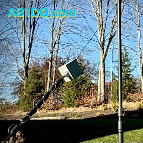
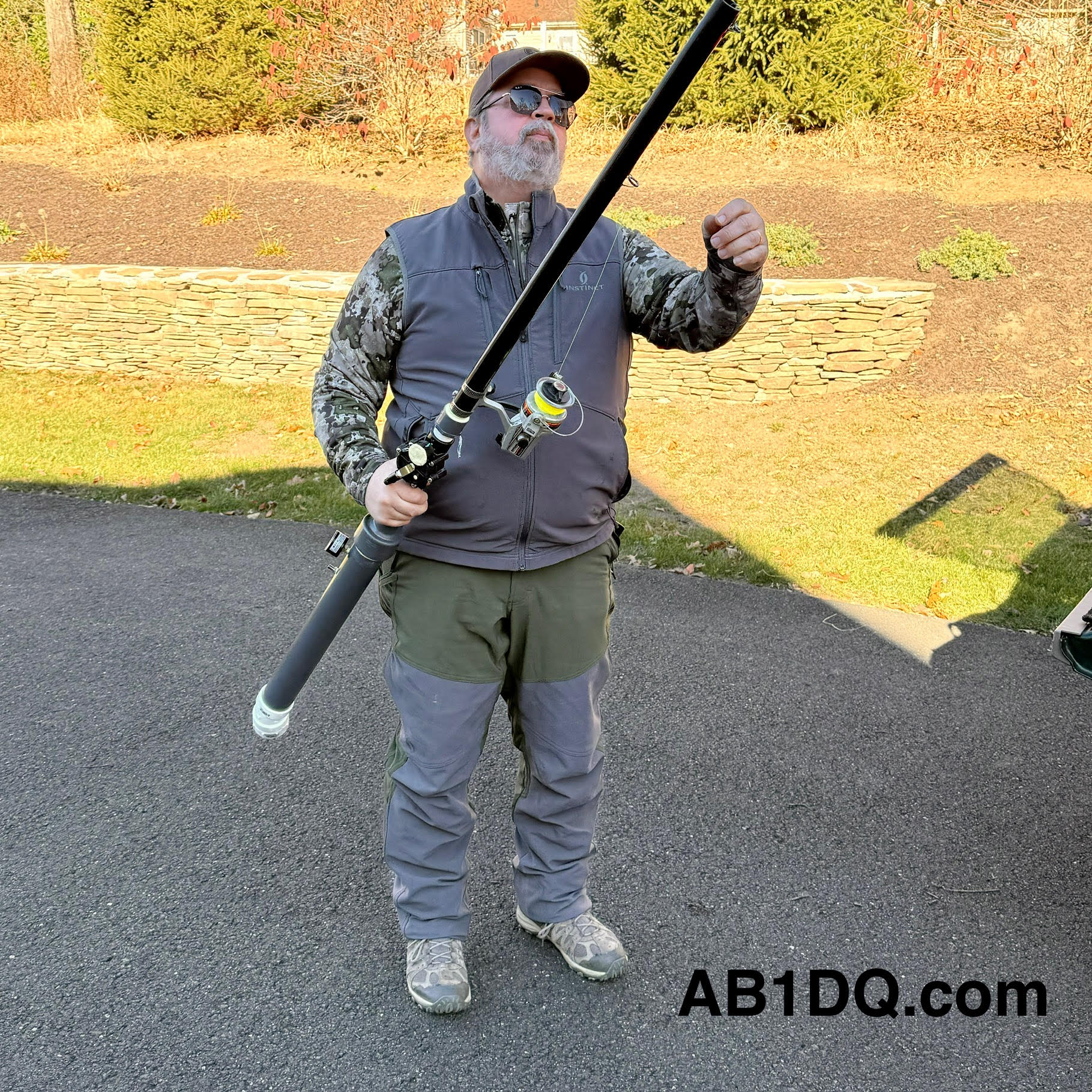
NOV. 16: OF SPUD GUNS & FELLOWSHIP
This past Saturday, November 16 brought more mild weather, and as our usual Saturday morning club open house was canceled that day due to a scheduling conflict at the OEM, it made it possible for me to get with Rob, K1RCT, our club’s station manage and an all-around good guy, who brought his mighty spud gun to my QTH to help me complete the installation of the antenna.
I always enjoy Rob’s company and his willingness to share his radio expertise. Years ago, our former club president, Bill W1KKF/SK made a couple of trips out here to Cheshire with his bow and arrow to help me string wires in the trees. I was always grateful to Bill for his help and his presence is missed by all who knew him. But now, Rob has brought antenna launching to a whole new level with his spud gun.
Prior to Rob’s arrival, I had tied off the feed point end of the antenna. A short run of coax extends from my transceiver to the Common Mode Choke placed on the windowsill of my 2nd floor shack.
A 3′ coax jumper connects the CMC to the 49:1 un-un on the other side of the window. I used a pool noodle as a pass-through. I drilled a small diameter hole matching the size of the jumper, and then using a razor blade, made a slit extending from each hole to allow me to feed the cable with the PL-259 through. The pool noodle makes for an inexpensive, easy and insulated feedline pass through.
The antenna then begins from the top lug on the un-un, extending a few feet to a dogbone inserted for strain relief. A short length of rope is tied off to the eyelet on the top of the un-un and is passed through a galvanized steel eye hook attached adjacent to the top of the window pane.
Here are a few final photos of the end of the antenna raising.


NOV. 17: ON THE AIR
My timing to complete the antenna project couldn’t have been better as this past weekend was the ARRL November Phone Sweeps – my favorite contest (as a non-contester). In years past, my goal for both the CW & Phone Sweeps was to beat my score from the prior year.
I am happy to report that I made 60 contest contacts, operating at my leisurely pace for a couple of hours. I searched and pounced and was able to work nearly every station I called on 40, 20, and 15 meters. The map seems to suggest the antenna performs as intended…

Did you have a fall antenna project? Have you used an end-fed half-wave antenna and what is your impression of the design? Leave a comment or drop me an email at james@ab1dq.com and let me know what you think.
Published November 19, 2024
©2024 JMSurprenant
